Cooler for steel rails

A cooling device and rail technology, which is applied to furnaces, heat treatment equipment, heat treatment furnaces, etc., can solve the problems of low cooling efficiency of cooling devices and inability to meet the cooling requirements of high-strength bainitic rails at the same time, so as to improve cooling efficiency and improve welding. quality, the effect of increasing the cooling rate

Active Publication Date: 2015-10-07
PANZHIHUA IRON & STEEL RES INST OF PANGANG GROUP
View PDF7 Cites 11 Cited by
  • Summary
  • Abstract
  • Description
  • Claims
  • Application Information

AI Technical Summary

Problems solved by technology

However, the cooling efficiency of the above cooling devices is still low, and cannot meet the cooling re

Method used


Image

  • Cooler for steel rails
  • Cooler for steel rails

Examples


Example Embodiment

[0034] Specific embodiments of the present invention will be described in detail below in conjunction with the accompanying drawings. It should be understood that the specific embodiments described here are only used to illustrate and explain the present invention, and are not intended to limit the present invention.

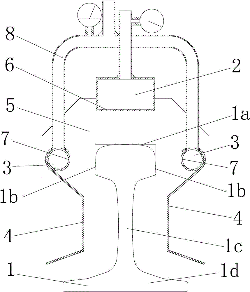
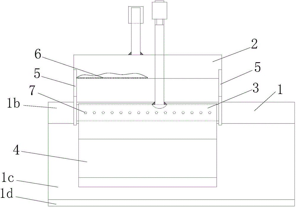
[0035] The invention provides a cooling device for rails, such as figure 1 and figure 2 As shown, the cooling device includes an air cooler for cooling the head of the rail, and the cooling device also includes an air deflector 4 arranged on both sides of the rail 1 and extending along the extending direction of the rail 1. A cooling air guide space is formed between the air deflector 4 and the sides of the rail, (the local area between the air deflector 4 and the head, waist 1c and bottom 1d of the rail), so as to guide the cooling wind from the head of the rail Flows down through the waist 1c and bottom 1d of the rail.

[0036] It should be noted that the ...


PUM


Abstract

The invention relates to the field of railways, and discloses a cooler for steel rails, which comprises an air cooler for cooling a steel rail head, and air guide plates (4) which are arranged on both sides of the steel rail (1) and extend along the extension direction of the steel rail (1), wherein an air guide space is respectively formed between the air guide plates (4) and the two side surfaces of the steel rail so as to guide the cooling air to flow through the waist (1c) and bottom (1d) of the steel rail downwardly from the steel rail. The cooler has higher cooling rate for the waist and bottom of the steel rail, enhances the steel rail cooling efficiency, and further can enhance the welding quality of the steel rail joint.

Description

technical field [0001] The invention relates to the field of railways, in particular to a cooling device for steel rails. Background technique [0002] The rails of the track generally need to be welded (whether it is flash welding of the welding rail base, or the aluminothermic welding on the railway site, or air pressure welding) to form a seamless line in order to improve the smoothness of the railway and ensure the smooth operation of the train. According to the requirements of the iron standard (TB / T1632-2005 series standards), flash welding and gas pressure welding need to be subjected to post-weld normalizing heat treatment process to refine the structure, improve the strength and toughness of the joint, make the hardness distribution of the top surface of the rail head reasonable and release welding purpose of stress. Years of data statistics show that the probability of damage to rail welded joints is much greater than that of the rail base metal itself. Therefore,...

Claims


Application Information

Patent Timeline
IPC IPC(8): C21D9/04
Inventor 李大东邓健余腾义白威王春建王若愚
Owner PANZHIHUA IRON & STEEL RES INST OF PANGANG GROUP
Why Eureka
Try Eureka