Multi-stage vertical high specific speed mixed-flow pump

A high specific speed, mixed-flow pump technology, applied in non-variable pumps, components of pumping devices for elastic fluids, pumps, etc., can solve the problem of chaotic flow state at the inlet of the pump impeller, unachievable engineering transformation, pump set Unable to hoist in and other problems, to achieve the effect of wide application range, widening the use range of the head, and a wide range of use

Inactive Publication Date: 2015-10-07
HUNAN NANFANG CHANGHE PUMP IND
View PDF9 Cites 10 Cited by
  • Summary
  • Abstract
  • Description
  • Claims
  • Application Information

AI Technical Summary

Problems solved by technology

When the pump foundation hole in the pump renovation project cannot be re-constructed and changed, the single-stage vertical mixed-flow pump we use has a relatively high lift, but the specific speed of the pump is small, and the efficiency is reduced. The larger the radial size of the blade body, the larger the diameter of the guide vane body of the single-stage pump, the pump unit cannot be hoisted into the pump foundation hole, and the engineering transformation cannot be realized
The general water pump can increase the number of stages in order to increase its head, but the outlet of the guide vane of the vertical mixed flow pump is much larger than the diameter of the impeller inlet. If there are multiple stages directly transitioning, the inlet flow state of the pump impeller will be seriously confused, and the efficiency of the pump will be greatly reduced. Therefore, vertical mixed-flow pumps are all single-stage structures.

Method used


Image

  • Multi-stage vertical high specific speed mixed-flow pump
  • Multi-stage vertical high specific speed mixed-flow pump
  • Multi-stage vertical high specific speed mixed-flow pump

Examples


Embodiment Construction

[0031] In order to enable those skilled in the art to better understand the technical solution of the present invention, the present invention will be described in detail below in conjunction with the accompanying drawings. The description in this part is only exemplary and explanatory, and should not have any limiting effect on the protection scope of the present invention. .

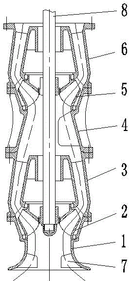
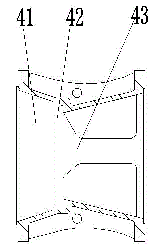
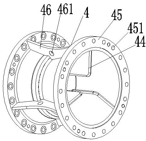
[0032] like Figure 1-3 As shown, the structural connection relationship of the present invention is a multi-stage vertical high specific speed mixed flow pump, which includes a suction bell mouth 1 and a drive shaft 8 arranged in the center; the upper end of the suction bell mouth 1 is connected with a first-stage guide vane body 3; the upper end of the first-stage guide vane body 3 is connected with a secondary guide vane body 6; a first-stage impeller 2 is arranged between the suction bell mouth 1 and the first-stage guide vane body 3; the first-stage guide vane body 3 and the secondary guide vane ...


PUM


Abstract

The invention discloses a multi-stage vertical high specific speed mixed-flow pump which comprises a suction cone and a drive shaft arranged in the center. The upper end of the suction cone is connected with primary guide vane bodies, the upper end of each primary guide vane body is connected with a secondary guide vane body, a primary vane wheel is arranged between the suction cone and the primary guide vane bodies, and a secondary van wheel is arranged between the primary guide vane bodies and the secondary guide vane bodies; the primary vane wheel and the secondary vane wheel are both arranged on the drive shaft, and middle transition joints are connected between the primary guide vane bodies and the secondary guide vane bodies; the secondary vane wheel is arranged between the middle transition joints and the secondary guide vane bodies; each middle transition joint is provided with a leading-in cavity which is connected with a leading-out cavity, a transition opening is formed between each leading-in cavity and the corresponding leading-out cavity, the inner walls of the leading-in cavities are all provided with transitional flow deflectors, and the two ends of each middle transition joint are provided with connecting flanges. According to the multi-stage vertical high specific speed mixed-flow pump, the lift is high, the flow is large, the efficiency is high, the size is small, the production cost is low, the installation is convenient, and the practical range of the vertical mixed-flow pump is greatly widened.

Description

technical field [0001] The invention relates to the technical field of water pump design, in particular to a multistage vertical high specific speed mixed flow pump. Background technique [0002] Mixed flow pump is a kind of pump between centrifugal pump and axial flow pump. Its impeller has both centrifugal force and axial thrust on the liquid. It is a combination of centrifugal pump and axial flow pump, and the liquid flows out of the impeller obliquely. It is mainly used to transport clean and polluted media, chemically neutral or aggressive media, forced circulation in chemical processes, mariculture, city gas engineering, and water treatment systems. [0003] The specific speed range of the vertical mixed flow pump is between 170-600, and the specific speed of the high specific speed mixed flow pump is generally greater than 200, which has high efficiency, large flow rate and low head. When the pump foundation hole in the pump renovation project cannot be re-constructe...

Claims


Application Information

Patent Timeline
Patent Type & Authority Applications(China)
IPC IPC(8): F04D13/06F04D29/18F04D29/40
Inventor 伍春花陈云王辉
Owner HUNAN NANFANG CHANGHE PUMP IND
Why Eureka
Try Eureka