Liquid conveying hose

A technology of liquid and tubular fabrics, which is applied in the direction of hoses, pipes, pipes/pipe joints/fittings, etc., which can solve the problems that the hose is difficult to flatten or fold, limit the length of the hose, and reduce the softness, so as to achieve convenient coiling Or folded storage, increase the delivery flow, the effect of good softness

Inactive Publication Date: 2015-10-07
祝锦聪
View PDF6 Cites 9 Cited by
  • Summary
  • Abstract
  • Description
  • Claims
  • Application Information

AI Technical Summary

Problems solved by technology

These two kinds of hoses have common disadvantages: the length of the hose is limited: because the inner and outer rubber layers of the adhesive lining need to have an operating platform as long as the hose, the length of the operating platform limits the length of the hose
[0003] On the other hand, in the prior art, there is also a single-layer hose reinforcement layer. In order to improve the pressure bearing strength of the hose, the fineness of the warp and weft yarns and the density of the warp and weft yarns are increased. Due to the limitations of the structure and production equipment, There are the following disadvantages: (a) simply increasing the denier of the reinforced layer will reduce the softness of the reinforced layer and the corresponding hose products, making it difficult to flatten or fold the hose; (b) the increase in the thickness of the reinforced layer also increases the subsequent inner and outer rubber layers The difficulty of the coating process, the hose is difficult to form

Method used


Image

  • Liquid conveying hose

Examples


Embodiment Construction

[0012] The present invention is described in detail below with reference to the accompanying drawings, in which like reference numerals denote like parts. In order to achieve the above purpose, the following technical solutions are adopted:

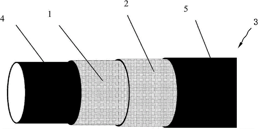
[0013] figure 1 It shows a schematic structural diagram of an embodiment of the liquid delivery hose 3 of the present invention, which includes: an inner rubber layer 4 , a tubular fabric layer 1 , a soft wire mesh layer 2 and an outer rubber layer 5 from inside to outside.

[0014] The inner rubber layer 4 and the outer rubber layer 5 are made of thermoplastic polyurethane body material or thermoplastic polyurethane added with additives.

[0015] The tubular fabric layer 1 can be plain weave, twill weave or satin weave structure. The plain weave structure is denser and the shape retention is better. As the floating point number increases in the twill weave, the enhancer layer becomes looser, but the pressure resistance performance will...


PUM


Abstract

The invention discloses a manufacturing method for a liquid conveying hose. The method comprises the steps that a cylindrical fabric layer is woven through a circular weaving machine, wherein the cylindrical fabric layer is of an independent plain weave structure, or twill weave structure or satin weave structure; the cylindrical fabric layer is dried; a flexible wire mesh is wound outside the cylindrical fabric layer; the structure obtained through the step (3) is coated with thermoplastic polyurethane after sized dicing and melting, so that an inner bond layer and an outer bond layer are formed, and the hose is manufactured. According to the hose, the flexible wire mesh is added, high liquid conveying pressure can be borne, and the conveying flow of the hose is further improved.

Description

technical field [0001] The invention relates to a liquid hose. Background technique [0002] Existing flat-coiled liquid conveying hoses are film-lined hoses. This type of hose currently has two structures, one is to thermally coat the inner and outer rubber layers of the hose with elastomer materials inside and outside the tube blank of the synthetic fiber circular weave. In order to prevent the hose from leaking, the inner wall of the hose is again glued with a leak-proof film layer with good sealing performance. Another structure is that the inner and outer rubber layers of the hose are formed by sticking a protective layer and a sealing layer on the inside and outside of the synthetic fiber circular-woven tube blank. These two kinds of hoses have common disadvantages: the length of the hose is limited: because the inner and outer rubber layers of the adhesive lining need to have an operating platform equal to the length of the hose, the length of the operating platform...

Claims


Application Information

Patent Timeline
Patent Type & Authority Applications(China)
IPC IPC(8): F16L11/08
CPCF16L11/081F16L11/085
Inventor 祝锦聪
Owner 祝锦聪
Why Eureka
Try Eureka