Measuring device and method for pulsed ion beam cross section image

A pulsed ion beam and cross-sectional image technology, applied in the field of accelerators, can solve problems such as high repetition times, poor cross-sectional image accuracy, and high ion beam current intensity, and achieve the effects of easy preparation, easy purchase, and simple equipment and materials

Inactive Publication Date: 2015-10-07
INST OF NUCLEAR PHYSICS & CHEM CHINA ACADEMY OF
View PDF7 Cites 7 Cited by
  • Summary
  • Abstract
  • Description
  • Claims
  • Application Information

AI Technical Summary

Problems solved by technology

[0003] At present, all methods for measuring and observing the size and shape of the pulsed ion beam spot have obvious deficiencies: the focal spot observation method requires a large number of ion beams to bombard metal materials to produce burnt and dead etching marks, forming the so-called focal spot
This method requires high ion beam intensity and many repetitions, so it is not suitable for the observation of pulsed ion beams, especially single pulsed ions; the beam current measurement method on the aperture and on the target needs to measure the pulsed ions on the target and the aperture respectively. Current, this method takes a long time to measure, and can only obtain the distribution of pulsed ion beams. The visible light of the fluorescent target will also produce a response, so the accuracy of the cross-sectional image is poor

Method used


Image

  • Measuring device and method for pulsed ion beam cross section image

Examples


Embodiment 1

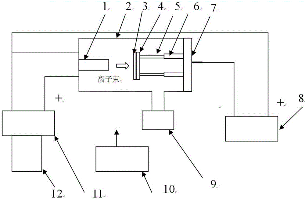
[0023] figure 1 It is a structural schematic diagram of the present invention, in figure 1 Among them, the measuring device of the pulsed ion beam section image of the present invention includes 1. ion source, 2. quartz glass tube, 3. imaging plate, 4. aluminum liner, 5. adjustable pitch screw, 6. adjustable pitch nut, 7. Stainless steel flange, 8. Adjustable acceleration power supply, 9. Vacuum unit, 10. Imaging analyzer, 11. Ion source pulse power supply, 12. Isolation transformer.

[0024] An aluminum liner 4 is set at the target position of the measurement device for the pulsed ion beam cross-sectional image, and the imaging plate 3 is fixed on the aluminum liner 4, and the plate surface is perpendicular to the running direction of the pulsed ion beam; open and adjust the high voltage value of the accelerating power supply 8 to 30kV; the vacuum in the quartz glass tube 2 in the measuring device is pumped to 5×10 by the vacuum unit 9 -4 Pa, adjust the output pulse of the ...

Embodiment 2

[0026] The structure of this embodiment is the same as that of Embodiment 1, and the implementation process is the same, the difference is: adjust the high voltage value of the accelerating power supply 8 to 120kV; set the output pulse repetition frequency of the ion source pulse power supply 10 to 0.1Hz; 10 Start timing, and the measurement time is 20s.


PUM


Abstract

The invention provides a measuring device and method for a pulsed ion beam cross section image, and especially provides a measuring device and method for a pulsed ion beam cross section image with a continuous adjustable acceleration voltage, and with a single pulse or an adjustable pulse frequency. An imaging plate is installed in a target position of the measuring device. High vacuum inside the measuring device is achieved by utilization of a vacuum unit. When the pulse ion source of the measuring device discharges, a cathode material is ionized, and plasma is generated. When a high-voltage pulse is applied at a guiding-out electrode, a pulse ion beam is guided out and hits on the imaging plate. After the imaging plate receives the pulse ion beam, a sensitive layer is excited and carries the ion beam distribution latent image. After the imaging plate is taken out from the pulse ion beam cross section image measuring device, an imaging analyzer releases hard light and thus de-excitation of the sensitive layer is carried out, the latent image is converted into an optical image, then the optical image is converted into a digital image, and then the digital image is transmitted to a computer. The shape of the image can be observed conveniently, and transverse dimension and vertical dimension of a beam spot can be measured quantificationally.

Description

technical field [0001] The invention belongs to the technical field of accelerators, and in particular relates to a measuring device and method for a pulsed ion beam cross-sectional image, in particular to a measuring device and method for a pulsed ion beam cross-sectional image with adjustable accelerating voltage, single pulse or adjustable pulse frequency. Background technique [0002] Pulse accelerators are widely used in the field of nuclear technology. Pulsed neutron tubes have important applications in the fields of non-destructive testing and pulsed neutron logging. The working principle of the pulse accelerator and pulse neutron tube is to generate pulse deuterium ions by pulse ion source discharge, pulse deuterium ions are accelerated by the accelerating electrode and hit the tritium target to form deuterium-tritium fusion reaction to generate 14MeV pulse neutrons. After the pulsed ion beam is extracted from the ion source, part of it hits the target, and due to i...

Claims


Application Information

Patent Timeline
Patent Type & Authority Applications(China)
IPC IPC(8): G01T3/00
Inventor 周长庚柯建林邱瑞
Owner INST OF NUCLEAR PHYSICS & CHEM CHINA ACADEMY OF
Why Eureka
Try Eureka