
Traction motor rotor commutator chamfering machine

A traction motor and commutator technology, which is applied in the field of metal processing, can solve the problems of uneven commutator chamfering and low chamfering efficiency, and achieve the effects of simple structure, high processing efficiency, and stable chamfering straightness

Inactive Publication Date: 2015-10-07
ZIBO SUPER MOTOR
View PDF5 Cites 2 Cited by
  • Summary
  • Abstract
  • Description
  • Claims
  • Application Information

AI Technical Summary

Problems solved by technology

[0004] In order to solve the problems of uneven commutator chamfering and low chamfering efficiency, the invention provides a traction motor rotor commutator chamfering machine

Method used


Image

  • Traction motor rotor commutator chamfering machine

Examples


Embodiment Construction

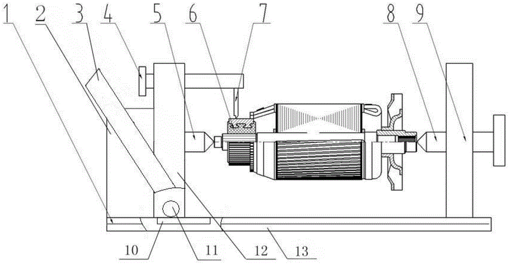
[0016] Such as figure 1 As shown, a traction motor rotor commutator chamfering machine includes a front bracket 2 and a rear bracket 9 fixed on the bottom bracket 13, the front bracket 2 is provided with a top 5, and the rear bracket 9 is provided with a moving top 8, The top 5 and the moving top 8 respectively fix the center of both ends of the workpiece, and adjust the moving top 8 to adapt to workpieces of different lengths.

[0017] Between the front bracket 2 and the rear bracket 9, there is a knife rest 12, the knife rest 12 is connected to the power rod 3, the power rod 3 is linked with the gear 11 at the bottom of the knife rest, the gear 11 meshes with the rack 10 at the bottom of the guide rail 1, and the power rod 3 is shaken When the gear 11 rotates, through the meshing of the gear 11 and the rack 10 , the rotational motion is converted into a linear motion, thereby driving the tool holder 12 to move along the guide rail 1 . The knife holder 12 is provided with a ...


PUM


Abstract

The invention relates to the field of metal processing, and particularly relates to a traction motor rotor commutator chamfering machine, which comprises a front support and a rear support arranged at two ends of a bottom support. The front support is provided with a center, the rear support is provided with a mobile center, a tool carrier is arranged between the front support and the rear support, the tool carrier moves along a guide rail, a scraper is arranged on the tool carrier, and the scraper is provided with two blades. According to the traction motor rotor commutator chamfering machine, the structure is simple, two centers are adopted for positioning, the two centers are ensured to be in the same axial direction, a precious guide rail is used for driving the tool carrier to move, chamfering straightness is ensured to be stable, chamfering is ensured to be uniform, chamfering is carried out on commutating segments at two sides at one time in the case of processing, and the processing efficiency is high.

Description

technical field [0001] The invention relates to the field of metal processing, in particular to a chamfering machine for a rotor commutator of a traction motor. Background technique [0002] As the problem of environmental pollution is becoming more and more severe, electric vehicles have been widely used. At the same time, the traction motors supporting electric vehicles have also been greatly developed, and the requirements for their quality are gradually increasing. [0003] At present, the chamfering of the commutator of the DC brush motor is usually performed by manual chamfering twice, which is easy to cause problems such as uneven chamfering after processing, poor chamfering straightness, unstable quality, etc., causing motor commutation sparks Large, unstable positive and negative rotation speed, large motor friction resistance and other adverse effects, resulting in unstable quality of the motor, easy to burn out, and have a negative impact on the market. Contents...

Claims


Application Information

Patent Timeline
Patent Type & Authority Applications(China)
IPC IPC(8): H01R43/06
Inventor 吕宏
Owner ZIBO SUPER MOTOR
Learn More