Automatic cable peeling system apparatus equipped with cable sheath recovery box

A system device and recovery box technology, applied in the direction of dismantling/armored cable equipment, etc., can solve the problems of high repair cost, high labor intensity of workers, pollution of the environment, etc., to facilitate stripping with a knife, improve stripping efficiency, and quickly The effect of stripping

Inactive Publication Date: 2015-10-07
成都新三电线厂
View PDF6 Cites 7 Cited by
  • Summary
  • Abstract
  • Description
  • Claims
  • Application Information

AI Technical Summary

Problems solved by technology

At present, there are two peeling methods, one is manual peeling, the worker cuts the insulation and sheath layer vertically and horizontally with a blade, and then pulls them off one by one, the disadvantages are: time-consuming and laborious, extremely low efficiency, and labor intensity of workers , prone to hand injury accidents; the other is to burn the insulation layer and sheath layer with fire. The disadvantages are: plastic and rubber smoke seriously pollute the environment and do not meet environmental protection requirements; it is difficult to remove the smoke and dust on the surface of the core; the metal core ( Especially the mechanical properties of copper core wire) will change due to high temperature, and need to be reheated; resulting in high repair costs

Method used


Image

  • Automatic cable peeling system apparatus equipped with cable sheath recovery box
  • Automatic cable peeling system apparatus equipped with cable sheath recovery box

Examples


Embodiment 1

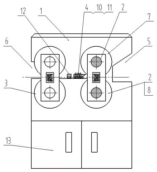
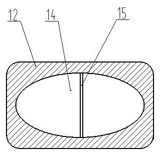
[0015] like figure 1 A cable automatic stripping system device with a wire sheath recovery box shown, including a box body 1, an incoming wire roller assembly 2, an outgoing wire roller assembly 3 and a wire stripping knife assembly 4, is characterized in that the incoming wire The roller assembly 2 is arranged at the inlet 5 of the box body 1, the outlet roller assembly 3 is arranged at the outlet 6 of the box body 1, and the stripping knife assembly 4 is arranged at the inlet roller Between the assembly 2 and the outlet roller assembly 3, the inlet roller assembly 2 includes an upper inlet roller 7 and a lower inlet roller 8, and the upper inlet roller 7 and the lower inlet roller (8 ) with a heating device 9 inside. A wire sheath separation device 12 is arranged behind the wire stripping knife assembly 4 , and a wire sheath recovery box 13 is arranged in the box body 1 below the separation device 12 .

[0016] A heating device 9 is installed in the wire inlet roller assem...

Embodiment 2

[0018] like figure 1 Shown is an automatic cable stripping system with a wire sheath recovery box. On the basis of Embodiment 1, the incoming wire roller assembly 2 and the outgoing wire roller assembly 3 rotate synchronously.

Embodiment 3

[0020] like figure 1 Shown is an automatic cable stripping system device with a wire sheath recovery box. On the basis of Example 1, the heating device (9) is a silicon carbide rod.


PUM


Abstract

The invention discloses an automatic cable peeling system apparatus equipped with a cable sheath recovery box. The apparatus includes a box body, a cable inlet roller assembly, a cable outlet roller assembly and a cable-peeling cutter assembly. The cable inlet roller assembly is arranged in an inlet of the box body. The cable outlet roller assembly is arranged in an outlet of the box body. The cable-peeling cutter assembly is arranged between the cable inlet roller assembly and the cable outlet roller assembly. The cable inlet roller assembly includes an upper cable inlet roller and a lower cable inlet roller, and heating devices are arranged in the upper cable inlet roller and the lower cable inlet roller. A cable sheath separating device is arranged behind the cable-peeling cutter assembly. A cable sheath recovery box is arranged in the box body below the separating device. Heating devices, arranged in a cable inlet roller assembly of a cable peeling machine, heat cable sheaths before cables are peeled, the cable sheaths are usually rubber materials and become softened and expand after being heated, and the softened cable sheaths are greatly reduced in toughness so as to be convenient to peel by a peeling cutter. Moreover, after the cable sheaths are peeled, the cable sheaths can be easily separated from a cable core, so the cable peeling efficiency is improved.

Description

technical field [0001] The invention relates to the field of cable recovery, in particular to an automatic cable stripping system device with a cable sheath recovery box. Background technique [0002] In the wire and cable manufacturing process, due to various reasons, some unqualified products will appear, and the plastic or rubber insulating layer and sheath layer of these unqualified products need to be removed and reprocessed. At present, there are two peeling methods, one is manual peeling, the worker cuts the insulation and sheath layer vertically and horizontally with a blade, and then pulls them off one by one, the disadvantages are: time-consuming and laborious, extremely low efficiency, and labor intensity of workers , prone to hand injury accidents; the other is to burn the insulation layer and sheath layer with fire. The disadvantages are: plastic and rubber smoke seriously pollute the environment and do not meet environmental protection requirements; it is di...

Claims


Application Information

Patent Timeline
Patent Type & Authority Applications(China)
IPC IPC(8): H02G1/12
Inventor 吴善同
Owner 成都新三电线厂
Why Eureka
Try Eureka