Vehicle road mobile charging system

A mobile charging and road technology, applied in electromagnetic wave systems, vehicle components, information technology support systems, etc., can solve problems such as serious electromagnetic radiation, unfavorable promotion of mobile charging systems, and inability to support electric vehicle charging.

Inactive Publication Date: 2015-10-07
李高山
View PDF4 Cites 13 Cited by
  • Summary
  • Abstract
  • Description
  • Claims
  • Application Information

AI Technical Summary

Problems solved by technology

[0006] Although the first two electric vehicle charging methods are relatively simple and mature in technology, with high conversion efficiency and high output power, they cannot support the charging of electric vehicles during driving.
In the magnetic field resonance method, laying charging coils under the roadway has high construction costs, difficult management and maintenance, serio

Method used


Image

  • Vehicle road mobile charging system
  • Vehicle road mobile charging system
  • Vehicle road mobile charging system

Examples


Embodiment Construction

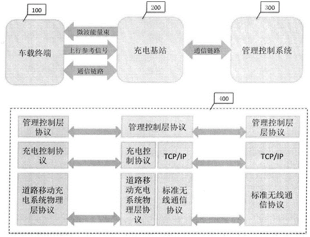
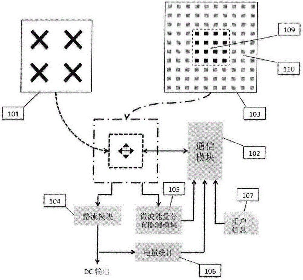
[0037] This patent does not involve the specific communication protocol and frame structure between the vehicle-mounted terminal 100 and the charging base station 200, nor does it involve the specific implementation of related hardware. The system parameters in the following application examples are only based on theoretical calculations, not the best engineering values ​​of the R&D design. They are only used to illustrate the feasibility of the patent, and one of the application scenarios is listed to help understanding.

[0038] Figure 12 Reference numerals 500 and 501 in are two adjacent charging base stations with a distance of 100m and installed at a height of 30m from the ground. The size of the vehicle-mounted terminal energy collection antenna 103 is 1.8m long along the road direction and 1.5m wide perpendicular to the road direction. Due to the existence of the control delay, sufficient edge margin must be reserved to ensure that the microwave main lobe energy will ...


PUM


Abstract

A vehicle road mobile charging system is an innovative system combining wireless microwave electric power transmission technologies and wireless communication technologies. The system makes up for the defect that electric vehicles are charged by fixed charging facilities. By means of the system, electric vehicles can be charged through microwave energy beams in a driving state. The means effectively increases the driving distance of pure electric vehicles, prevents defects of multi-time charging and long consumed time during a long distance trip and further makes a driver no longer worry about the mileage. The system comprises a vehicular terminal, a charging base station and a management control system. After successfully accessing to a charging network and being authorized, the vehicular terminal sends uplink reference signals. The charging base station receives the uplink reference signals through an antenna array and processes the signals to determine the orientation of vehicles. The microwave antenna array is further controlled according to the orientation information to send electric energy to a vehicle energy collecting and converting device in a microwave beam means. Closed-loop wave beam control technologies are adopted to guarantee that the energy beams are constantly aligned with the vehicular energy collecting device; and harm to surrounding objects is prevented.

Description

technical field [0001] The technical fields involved in the system include: microwave wireless power transmission technology, phased array antenna array and its signal processing technology, and mobile communication technology. Background technique [0002] Electric vehicle wireless charging technology includes three types: electromagnetic induction, magnetic field resonance and radio wave. [0003] Electromagnetic induction charging equipment includes a primary coil, a secondary coil and a rectifier circuit. The primary coil converts the input AC into an alternating magnetic field, the secondary coil induces a change in the magnetic field to generate current, and then converts the induced AC into a DC output through a rectifier. The primary coil is usually installed on the ground of the charging parking space, and the secondary coil is installed on the chassis of the electric vehicle. When charging, the secondary coil must face the primary coil. This charging method has h...

Claims


Application Information

Patent Timeline
IPC IPC(8): H02J7/00H02J17/00H02J13/00
CPCY02B90/20Y04S40/126
Inventor 李高山其他发明人请求不公开姓名
Owner 李高山
Why Eureka
Try Eureka