Liquid-cooling iron-coreless permanent-magnet linear motor

A permanent magnet linear motor, liquid cooling technology, applied in cooling/ventilation devices, electrical components, electromechanical devices, etc., can solve the problems of large primary loss, small rated thrust, and poor continuous output capability of the motor

Inactive Publication Date: 2015-10-07
HARBIN INST OF TECH
View PDF4 Cites 14 Cited by
  • Summary
  • Abstract
  • Description
  • Claims
  • Application Information

AI Technical Summary

Problems solved by technology

[0004] The purpose of the present invention is to provide a liquid-cooled ironless permanent magnet synchronous motor to solve the problems of poor continuous output capability, small rated thrust and large primary loss due to the natural cooling of the traditional double-sided ironless structure linear permanent magnet synchronous motor. Magnetic linear motor

Method used


Image

  • Liquid-cooling iron-coreless permanent-magnet linear motor
  • Liquid-cooling iron-coreless permanent-magnet linear motor
  • Liquid-cooling iron-coreless permanent-magnet linear motor

Examples


specific Embodiment approach 1

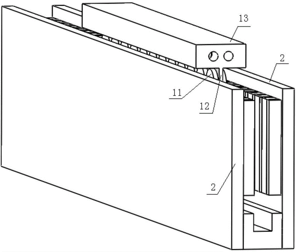
[0031] Specific implementation mode one: combine Figure 1 to Figure 3 ,as well as Figure 9 To illustrate this embodiment, the liquid-cooled coreless permanent magnet linear motor described in this embodiment includes a primary 1 and a secondary;

[0032] The primary includes a primary winding 11, a fixed plate 12 and a thrust output plate 13. The primary winding 11 is composed of 2km racetrack-shaped coils, wherein k is a positive integer, and m is the phase number of the motor; the fixed plate 12 is flat, and the primary winding 11 2km coils are symmetrically arranged on both sides of the fixed plate 12; the thrust output plate 13 is fixedly connected to one end of the fixed plate 12 along the moving direction;

[0033] The secondary is a bilateral structure, each secondary 2 includes a secondary iron core and a permanent magnet, the bilateral secondary 2 is arranged on both sides of the primary, and forms a series magnetic circuit, and two air gaps are formed between the ...

specific Embodiment approach 2

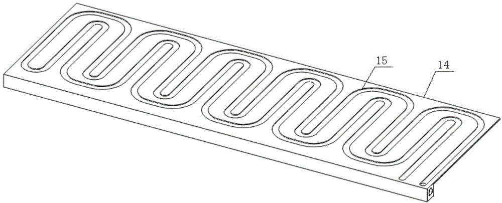
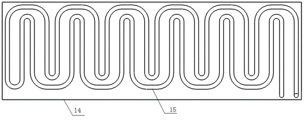
[0036] Specific implementation mode two: combination Figure 4 and Figure 5 This embodiment is described. This embodiment is a further limitation of the liquid-cooled coreless permanent magnet linear motor described in Embodiment 1. In this embodiment, the cooling liquid passage 15 is a parallel double-channel structure.

[0037] In this embodiment, dual-channel parallel cooling liquid channels are used to increase the contact area between the cooling liquid and the fixed plate 12 and improve the cooling effect.

specific Embodiment approach 3

[0038] Specific implementation mode three: combination combination Figure 6 and Figure 7 This embodiment is described. This embodiment is a further limitation of the liquid-cooled coreless permanent magnet linear motor described in Embodiment 2. In this embodiment, the primary winding 11 is dipped in paint and potted with epoxy resin.

[0039] In the coreless permanent magnet linear motor with natural cooling, the primary winding 11 is directly arranged on the fixed plate without cooling channels, or it is directly potted with epoxy resin without the fixed plate. The former has poor thermal conductivity, and the latter Poor strength. However, in this embodiment, the primary winding 11 is arranged on both sides of the fixing plate 12, dipped in paint, and then potted with epoxy resin with good thermal conductivity and high structural strength, so as to fix the primary winding 11 on the fixing plate 12. This structure At the same time, it has high strength and high thermal c...


PUM


Abstract

A liquid-cooling iron-coreless permanent-magnet linear motor belongs to the motor field. A traditional bilateral-iron-coreless-structure linear permanent-magnet synchronous motor adopts natural cooling so that a continuous output capability of the motor is poor; a rated thrust is small and a primary loss is large. By using the motor of the invention, the above problems are solved. A primary comprises a primary winding, a fixing plate and a thrust output plate. The primary winding is formed by 2km runway coils, wherein the k is a positive integer and the m is a phase number of the motor. The fixing plate is in a panel shape and a cooling fluid channel is arranged in the fixing plate. The 2km coils of the primary winding are symmetrically arranged on two sides of the fixing plate. The thrust output plate is fixedly connected to one end of the fixing plate along a motion direction. A secondary is a bilateral structure. Each edge secondary comprises a secondary iron core and a permanent magnet. The two edge secondaries are arranged on two sides of the primary and form a series magnetic circuit. Two air gaps form between the primary and the secondary. The continuous output capability of the motor is high, the rated thrust is large and the primary loss is less.

Description

technical field [0001] The invention relates to a liquid-cooled coreless permanent magnet linear motor, which belongs to the field of motors. Background technique [0002] The traditional bilateral ironless core structure linear permanent magnet synchronous motor (such as Figure 10 to Figure 12 As shown), the secondary is composed of a yoke plate and a flat permanent magnet. The permanent magnets are magnetized parallel to the direction perpendicular to the moving direction. Corresponding to the same magnetization direction of the permanent magnets, the primary is located between the two secondary plates. The normal component of the magnetic force line generated by the permanent magnet passes through the primary vertically, and the energized primary winding interacts with the magnetic field of the secondary permanent magnet to generate electromagnetic force and push the mover to move in a straight line. The linear motor with this structure has the characteristics of high t...

Claims


Application Information

Patent Timeline
Patent Type & Authority Applications(China)
IPC IPC(8): H02K41/03H02K9/19
Inventor 寇宝泉张鲁张赫陈宇声
Owner HARBIN INST OF TECH
Why Eureka
Try Eureka