Fluorescent light source device

A light source device and fluorescence technology, applied in the direction of fluorescence, light source, electric light source, etc., can solve the problems of low thermal conductivity of barium sulfate, complex driving system structure, inability to obtain a long service life of the wheel motor 73, etc., and achieve the effect of high luminous efficiency

Active Publication Date: 2015-10-07
USHIO DENKI KK
View PDF7 Cites 33 Cited by
  • Summary
  • Abstract
  • Description
  • Claims
  • Application Information

AI Technical Summary

Problems solved by technology

[0005] However, the configuration of the driving system of the fluorescent wheel 72 including the wheel motor 73 is complicated, and there is a problem that the wheel motor 73 cannot obtain a long service life due to deterioration of constituent members.
[0007] However, such a fluorescent light source device has the problem that high luminous efficiency cannot be obtained
[0008] Specifically, there is a problem that when the excitation light is irradiated to the wavelength conversion member 61, the excitation light is backscattered at the surface of the wavelength conversion member 61, so that the excitation light cannot be sufficiently absorbed into the wavelength conversion member 61. Inside of member 61
In addition, there is a problem that in the wavelength conversion member 61, among the fluorescence generated by the phosphor, the fluorescence whose incident angle exceeds the critical angle with respect to the interface between the wavelength conversion member 61 and air is enclosed in the inside of the wavelength conversion member 61, Therefore, the fluorescence cannot be effectively used
[0009] In addition, in the device described in Patent Document 2, there is a problem that since the fluorescence emitted from the phosphor is diffused in all directions and is emitted, it cannot be efficiently emitted from the side surface of the wavelength conversion member 61. to use
[0010] In addition, there is a problem that, since barium sulfate has low thermal conductivity, when barium sulfate is used as a diffuse reflection member, heat cannot be efficiently released.

Method used


Image

  • Fluorescent light source device
  • Fluorescent light source device
  • Fluorescent light source device

Examples


no. 1 Embodiment approach 》

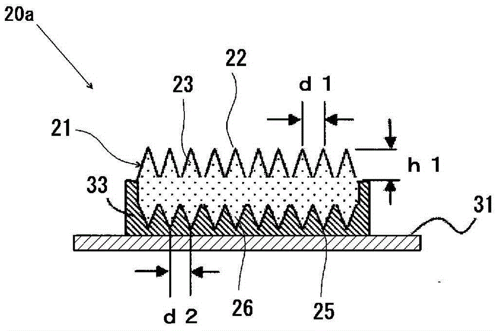
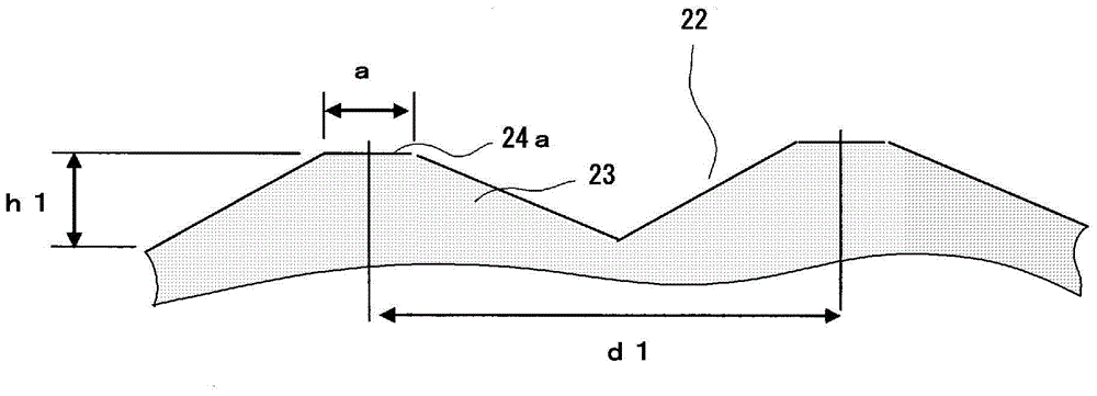
[0082] figure 2 It is an explanatory cross-sectional view showing the configuration of the fluorescent light emitting member in the fluorescent light source device according to the first embodiment of the present invention.

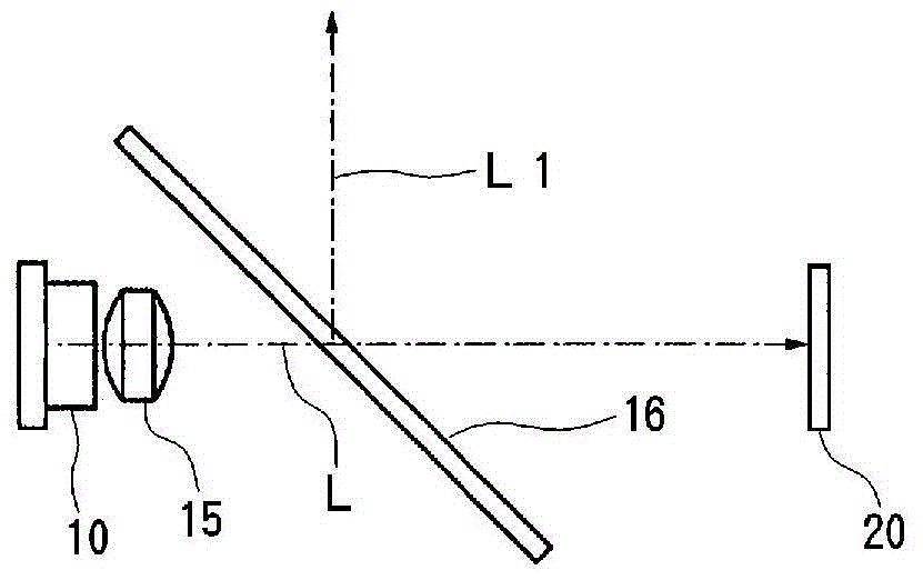
[0083] Fluorescent light emitting member 20a such as figure 2 As shown, on the surface of the rectangular substrate 31 ( figure 2 The upper surface of the upper surface) is provided with a wavelength conversion member composed of a substantially rectangular plate-shaped fluorescent member 21 .

[0084] The fluorescent light-emitting member 20a follows the surface of the fluorescent member 21 ( figure 2 The upper surface of the laser diode 10 is disposed so as to face the laser diode 10, and this surface serves as the excitation light receiving surface and also serves as the fluorescence emitting surface.

[0085] In addition, on the back of the fluorescent member 21 ( figure 2 The lower surface) and side surfaces are respectively provided with a ...

no. 2 Embodiment approach 》

[0161] Figure 8 It is an explanatory cross-sectional view showing the configuration of the fluorescent light emitting member in the fluorescent light source device according to the second embodiment of the present invention.

[0162] The fluorescent light emitting member 20b such as Figure 8 As shown, there is a rectangular substrate 31 and a wavelength conversion member formed of, for example, a rectangular plate-shaped fluorescent member 24 provided on the surface of the substrate 31 . In the fluorescent light-emitting member 20b of this example, the surface of the wavelength converting member ( Figure 8 The upper surface in the middle) becomes the light-receiving surface of the excitation light. The surface of the wavelength conversion member functions not only as an excitation light receiving surface, but also as a light emitting surface. Furthermore, on the excitation light receiving surface of the wavelength conversion member, that is, on the surface of the fluores...

no. 3 Embodiment approach 》

[0210] Figure 13 is an explanatory perspective view showing the configuration of the fluorescent light emitting member of the fluorescent light source device according to the third embodiment of the present invention, Figure 14 yes Figure 13 A cross-sectional view for explaining the fluorescent light-emitting member shown.

[0211] Fluorescent light emitting member 20c such as Figure 13 In the figure shown, a wavelength conversion member 122 composed of a rectangular flat fluorescent member is bonded to the surface of a rectangular flat substrate 121 via a rectangular bonding metal layer 129, and the peripheral side of the wavelength conversion member 122 is covered. A reflective layer 128 is formed in a manner.

[0212] The surface of the wavelength converting member 122 of the fluorescent light emitting member 20c ( Figure 14 The upper surface) becomes the excitation light receiving surface. In addition, the surface of the wavelength converting member 122 functions...


PUM

PropertyMeasurementUnit
thicknessaaaaaaaaaa
thicknessaaaaaaaaaa
thicknessaaaaaaaaaa

Abstract

Provided is a fluorescent light source device with which, when excitation light is emitted to a wavelength conversion member, rearward scattering of the excitation light is controlled and fluorescence generated inside the wavelength conversion member can be emitted to the outside with high efficiency, and with which high light-emitting efficiency can be obtained. The fluorescent light source device comprises a wavelength conversion member which uses phosphors that are excited by excitation light, and is characterized in that the wavelength conversion member has formed on a front surface thereof serving as an excitation light receiving surface a front-surface-side periodic structure, has formed on a rear surface thereof a rear-surface-side periodic structure, and has a light reflecting surface disposed on the outside of the rear surface.

Description

technical field [0001] The present invention relates to a fluorescent light source device that excites a phosphor with excitation light to emit fluorescence from the phosphor. Background technique [0002] As a green light source used in, for example, a projector, there has been known a fluorescent light source device that emits green light from a fluorescent body by irradiating laser light to the fluorescent body. As an example of such a fluorescent light source device, there is known a fluorescent light source device that includes a wavelength conversion member formed by coating a phosphor on the surface of a rotating wheel, and irradiates the wavelength conversion member with laser light in the blue region. , light in the green region is generated in the phosphor in the wavelength conversion member (see Patent Document 1). [0003] Specifically, in Patent Document 1, a fluorescent light source device as described below is used: Figure 17 As shown, a green light source o...

Claims


Application Information

Patent Timeline
Patent Type & Authority Applications(China)
IPC IPC(8): F21S2/00F21V9/16G03B21/14F21Y101/02
CPCG03B21/204C09K11/7774F21K2/00F21V7/22F21Y2101/00F21Y2115/30F21S41/16F21V13/14F21V9/32F21V7/30F21V13/08
Inventor 井上正树北村政治芜木清幸杉谷晃彦
Owner USHIO DENKI KK
Why Eureka
Try Eureka