Method and device for transmitting signals
A technology for transmitting signals and signals, which is applied in the field of transmitting signals and can solve problems such as the inability of user equipment and network equipment to transmit signals.
Active Publication Date: 2018-11-30
HUAWEI TECH CO LTD
4 Cites 0 Cited by
AI-Extracted Technical Summary
Problems solved by technology
[0004] After the system completes the configuration of the uplink transmission period and the downlink transmission period, the user equipment can only send uplink signals during the configured uplink transmission perio...
Method used
In dynamic TDD (that is, the configuration ratio of uplink and downlink subframes of TDD can be changed dynamically, the configuration ratios of uplink and downlink subframes of different network devices are different, thus causing different network devices to regard the same TTI as different uplink time periods/downlink time period) scenario, the first user equipment and the second network equipment use the same downlink subcarrier-frequency mapping method to send signals, that is, the first network equipment uses the same subcarrier-frequency mapping method to simultaneously receive signals from the first user equipment and the second network equipment A signal sent by the second network device (the signal sent by the second network device interferes with the signal sent by the first user equipment). The signal sent by the second network device may cause interference to the reception of the uplink signal sent by the first user equipment by the first network device. The first network device further instructs the first user equipment to use the same subcarrier-frequency mapping manner as that used by the second network device to send signals. In order to reduce interference, the second network device may send a resource occupation message to the first network device in advance to notify the first network device of the resources used by the second network device to send signals (resources include time, frequency, scrambling code or RS resource Wait). After receiving the resource occupation message, the first network device schedules resources for the first user equipment, and the resources overlap with the resources used by the second network device for sending signals. After the first network device receives the signals sent by the first user equipment and the second network device, it can reduce the interference caused by the signal sent by the second network device to the reception of the first network device by means of interference cancellation, and enhance the interference to the first user equipment. The reception performance of the signal sent by the device. The embodiment in which the first network device schedules the second network device and the first user equipment to use non-overlapping resources is the same as that described above, and will not be repeated here.
[0208] According to an embodiment of the present invention, the first device may use the first subcarrier-frequency mapping method to send the first signal during the first period, and send the second signal using the second subcarrier-frequency mapping method during the second period . Since the first device can use different subcarrier-frequency mapping methods (for example, the uplink and downlink subcarrier-frequency mapping methods shown in FIG. Network equipment) can flexibly perform uplink transmission or downlink transmission in the required time period, which improves the transmission performance of the system and improves the efficiency of frequency band usage.
[0214] It should be understood that the embodiments of the present invention do not limit the order of the first time period, the second time period and the third time period. For example, the third time period may be between the first time period and the second time period, or may be between the first time period Before or after the period or the second period. According to the embodiments of the present invention, user equipment or network equipment can flexibly adopt the uplink subcarrier-frequency mapping method or downlink subcarrier-frequency mapping method in the LTE system to receive or transmit signals according to service needs or scheduling strategies, thereby improving the system Transmission performance, and improve the use efficiency of the frequency band.
[0240] Since the first network device can receive the reference signals sent by the first user equipment and the second network device on different reference signal resources, interference between signals sent by the first user equipment and the second network device can be avoided .
[0246] Since the second user equipment can receive the reference signals sent by the first user equipment and the third network equipment on different reference signal resources, it is possible to avoid interference between signals sent by the first user equipment and the third network equipment .
[0265] According to an embodiment of the present invention, the first device may use the first subcarrier-frequency mapping method to receive the first signal during the first period, and receive the second signal using the second subcarrier-frequency mapping method during the second period . Since the first device can use different (for example, uplink and downlink) subcarrier-frequency mapping methods to receive signals in different time periods, the first device (for example, user equipment or network equipment) can flexibly use the required time period Performing uplink transmission or downlink transmission improves the transmission performance of the system and improves the use efficiency of the frequency band.
[0298] According to an embodiment of the present invention, the first network device can schedule the first device and the second network device to use the same subcarrier-frequency mapping method to transmit signals within the same period of time, thereby improving the flexibility of uplink and downlink transmission, The transmission performance of the system is improved, and the use efficiency of the frequency band is improved. In addition, because the same subcarrier-frequency mapping method is used to transmit signals during uplink transmission or downlink transmission in a subframe, the receiving end can reduce the reception frequency in this subframe by scheduling or interference cancellation. Interference between incoming signals.
[0306] Since the first user equipment and the second network equipment use the same downlink subcarrier-frequency mapping method to send signals, the impact of the signal sent by the second network equipment on the first user equipment can be reduced by scheduling or interference cancellation. Interference of the signal sent by the user equipment, so as to enhance the receiving performance of the first network device on the signal sent by the first user equipment.
[0307] Further, in this embodiment, a control node (not shown) can also be used to control or schedule the first network device and the second network device to send and receive signals, so that the second network device does not need to advance to the first network device Sending resource occupation information, for example, the control node controls the second network device to send a downlink signal to the second user equipment, and controls the first network device to schedule the same resource for the first user equipment to send the uplink signal and use the same resources as the second network device to send the signal. Using the same subcarrier-frequency mapping manner, the first network device is finally controlled to perform an interference cancellation operation to enhance the receiving performance of the uplink signal sent by the first user equipment.
[0309] In a wireless backhaul scenario, the first network device and the first user equipment use the same frequency to send useful signals to the second network device at the same time, and the second network device simultaneously receives and demodulates the two signals These two signals. In the conventional technology, the first network device sends downlink signals, and the user equipment sends uplink signals. Since the first network device and the first user equipment use different subcarrier-frequency mapping methods to send signals to the second network device, Therefore, the two signals have intercarrier interference with each other, making it difficult to cancel the interference. Different from the scenario described in FIG. 6, in this scenario, the first netwo...
Abstract
Embodiments of the present invention provide a method and device for transmitting signals. The method includes: the first device determines the first frequency corresponding to the first subcarrier used to map the first signal in the first period according to the first subcarrier-frequency mapping method, and sends the first signal on the first frequency; The first device determines the second frequency corresponding to the second subcarrier used to map the second signal in the second period according to the second subcarrier-frequency mapping method, and sends the second signal on the second frequency; wherein the first The subcarrier-frequency mapping method is different from the second subcarrier-frequency mapping method, and the first frequency and the second frequency belong to the same frequency band. The embodiment of the present invention can use the same subcarrier-frequency mapping method to transmit signals during uplink and downlink transmission within a period of time, which improves the transmission performance of the system and improves the use efficiency of the frequency band.
Application Domain
Spatial transmit diversitySignal allocation +3
Technology Topic
Frequency bandTransmission performance +1
Image
Examples
- Experimental program(1)
Example Embodiment
[0190] The technical solutions in the embodiments of the present invention will be clearly and completely described below in conjunction with the accompanying drawings in the embodiments of the present invention. Obviously, the described embodiments are part of the embodiments of the present invention, not all of them. Based on the embodiments of the present invention, all other embodiments obtained by those of ordinary skill in the art without creative work shall fall within the protection scope of the present invention.
[0191] It should be understood that the technical solution of the present invention can be applied to various communication systems, such as: GSM (Global System of Mobile communication, global mobile communication) system, CDMA (Code Division Multiple Access, Code Division Multiple Access) system, WCDMA (, Wideband Code) Division Multiple Access, broadband code division multiple access) system, GPRS (General Packet Radio Service, general packet radio service), LTE (Long Term Evolution) system, LTE-A (Advanced long term evolution, advanced long term evolution) system UMTS (Universal Mobile Telecommunication System, Universal Mobile Telecommunication System), etc. The embodiment of the present invention is not limited, but for the convenience of description, the embodiment of the present invention will take an LTE network as an example for description.
[0192] The embodiments of the present invention can be used in wireless networks of different standards. The wireless access network may include different network elements in different systems. For example, the network elements of the radio access network in LTE and LTE-A include eNB (eNodeB, evolved base station), and the network elements of the radio access network in WCDMA include RNC (Radio Network Controller, radio network controller) and NodeB, similar In addition, other wireless networks such as WiMax (Worldwide Interoperability for Microwave Access) can also use solutions similar to the embodiment of the present invention, except that the relevant modules in the base station system may be different. The embodiment of the present invention does not It is limited, but for the convenience of description, the following embodiments will take eNodeB as an example for description.
[0193] It should also be understood that, in the embodiments of the present invention, user equipment (UE, User Equipment) includes, but is not limited to, a mobile station (MS, Mobile Station), a mobile terminal (Mobile Terminal), a mobile telephone (Mobile Telephone), and a mobile phone (handset). And portable equipment (portable equipment), etc., the user equipment can communicate with one or more core networks via a radio access network (RAN, Radio Access Network). For example, the user equipment can be a mobile phone (or “cellular”). Telephone), computer with wireless communication function, etc., user equipment can also be portable, pocket-sized, handheld, built-in computer or vehicle-mounted mobile device or equipment.
[0194] The present invention is suitable for any wireless communication system, especially suitable for flexible duplex (Flexible Duplex) communication systems, involving service adaptation, interference adaptation, resource adaptation and other corresponding time-varying different uplink and downlink directions or duplexes The transmitting device or receiving device, that is, the involved device can change the allocation of uplink and downlink resources accordingly with changes in services, interference conditions, and resource utilization. The uplink and downlink resources include time resources and/or frequency resources.
[0195] In the LTE system, the uplink transmission and the downlink transmission adopt a multi-carrier transmission mode. For example, the user equipment or network equipment first encodes and modulates the data bits of the signal to be transmitted, and then maps them to the subcarriers through the Inverse Discrete Fourier Transform (IDFT) operation, and finally adds the cyclic prefix ( Cyclic Prefix, CP) and send it out.
[0196] The subcarrier mapping process is a process in which the transmitter places the signal stream generated by channel coding and modulation on the corresponding subcarrier according to a certain mapping method (for example, placing the i-th signal on the i+10th subcarrier). The signal reception process is reversed, that is, after the receiver removes the CP, it obtains the signal flow on the corresponding subcarrier according to the corresponding mapping mode of the transmitter, that is, performs the de-mapping operation (for example, obtains the i-th subcarrier from the i+10th subcarrier). Signals), I won’t repeat them here.
[0197] The signal received by the receiver is a superposition of waveforms with different frequencies and DC level. Since the energy of the DC level is very high, if the frequency corresponding to the DC level is used to send the useful signal, the useful signal will be greatly interfered by the DC level. Therefore, the frequency corresponding to the DC level is not used to transmit useful signals. This frequency is the middle frequency of the system bandwidth, hereinafter referred to as the direct current (DC) frequency.
[0198] The frequency (frequency point) corresponding to each sub-carrier of uplink transmission is different from the frequency corresponding to each sub-carrier of downlink transmission or is misaligned. In other words, the sub-carrier-frequency mapping method (or corresponding relationship) of uplink transmission is different from that of downlink transmission. Transmission sub-carrier-frequency mapping method. During uplink transmission, the user equipment’s signal transmission is limited by the requirement that the peak to average power ratio (PAPR) cannot be too high, so single-carrier frequency-division multiple access (Single-carrier Frequency-Division Multiple Access, SC -FDMA) mode to send the uplink signal, and the signal is required to be continuous in the frequency domain, that is, the signal must be mapped to the continuous sub-carrier in the frequency; in the downlink transmission, the signal sent by the network equipment is not restricted by PAPR, so the network equipment adopts more Flexible orthogonal frequency division multiple access (Orthogonal Frequency Division Multiple Access, OFDMA) way to send downlink signals, and does not require the signal to be continuous in the frequency domain.
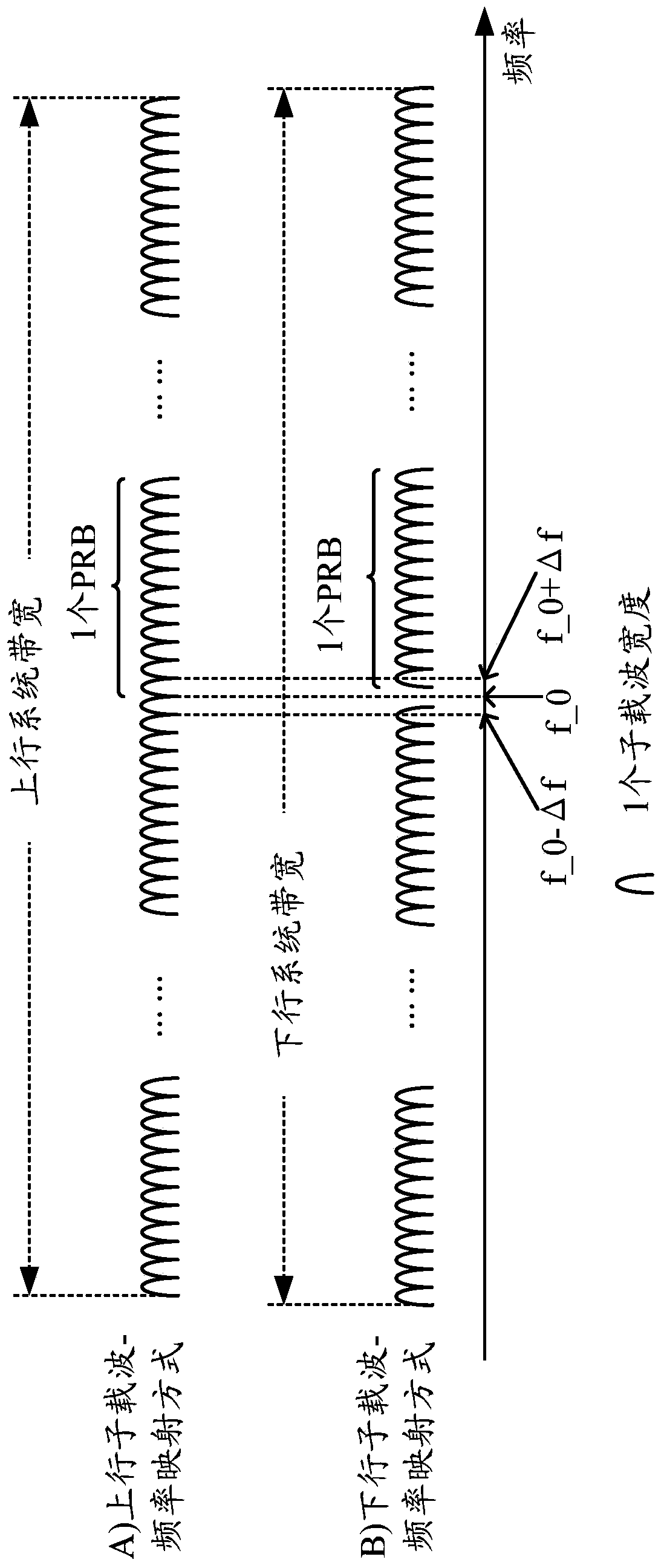
[0199] figure 1 It is a schematic diagram of the subcarrier-frequency mapping method for uplink transmission and downlink transmission. Such as figure 1 As shown, the middle point of a grid represents the frequency (or frequency point) of the subcarrier, where the middle frequency (ie, DC frequency) of the system bandwidth is f_0, and the subcarrier interval is Δf. For uplink transmission, the sub-carrier frequencies are f_0±1/2Δf, f_0±3/2Δf, f_0±5/2Δf,...; for downlink transmission, the sub-carrier frequencies are f_0±Δf, f_0±2Δf, f_0± 3Δf,.... in other words, figure 1 The shown uplink sub-carrier-frequency mapping method makes the frequencies of all sub-carriers and the most intermediate frequency of the system bandwidth separated by at least 1/2 sub-carrier width, while the downlink sub-carrier-frequency mapping method makes the frequencies of all sub-carriers and the system bandwidth The middle frequency is separated by at least 1 sub-carrier width, and the downlink transmission signal avoids the DC frequency. such, figure 1 The shown uplink subcarrier-frequency mapping mode and downlink subcarrier-frequency mapping mode have half subcarrier interleaving, that is, the frequencies to which the uplink subcarrier and the downlink subcarrier are mapped are different. Because the frequencies of the uplink and downlink subcarriers are misaligned, when the uplink and downlink signals are simultaneously sent on the same system bandwidth, the Inter-Carrier Interference (ICI) between the uplink and downlink signals is very serious.
[0200] It should be understood that for traditional frequency division duplex (Frequency Division Duplex, FDD) systems, the system bandwidths of uplink and downlink signals are different. The f_0 of the uplink signal mentioned above represents the middle frequency of the uplink system bandwidth. , The f_0 of the downlink signal represents the middle frequency of the downlink system bandwidth; for the traditional Time Division Duplex (TDD) system, the system bandwidth of the uplink and downlink signals is the same. The f_0 mentioned above is for the uplink The signal and the downlink signal represent the same frequency.
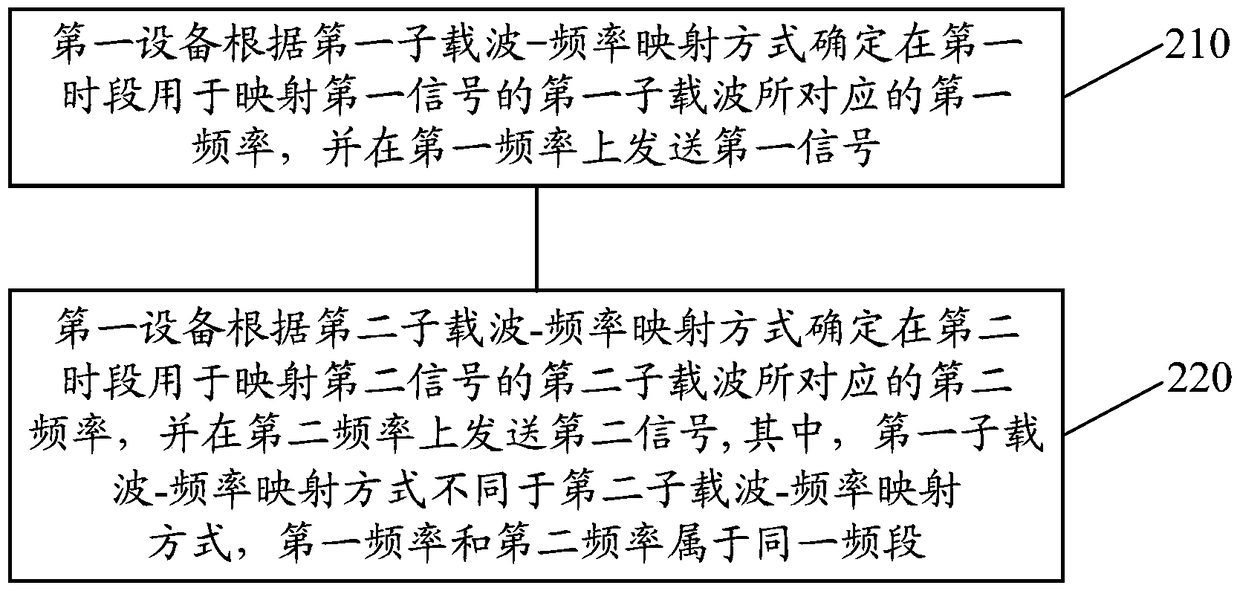
[0201] figure 2 It is a schematic flowchart of a signal transmission method according to an embodiment of the present invention. figure 2 The method can be executed by user equipment or network equipment (for example, a base station).
[0202] 210. The first device determines the first frequency corresponding to the first subcarrier used for mapping the first signal in the first time period according to the first subcarrier-frequency mapping (mapping) mode, and sends the first signal on the first frequency .
[0203] 220. The first device determines the second frequency corresponding to the second subcarrier used for mapping the second signal in the second time period according to the second subcarrier-frequency mapping mode, and transmits the second signal on the second frequency; wherein, The first subcarrier-frequency mapping method is different from the second subcarrier-frequency mapping method, and the first frequency and the second frequency belong to the same frequency band.
[0204] Either the first period and the second period may include at least one orthogonal frequency division multiple access OFDMA symbol or at least one single carrier frequency division multiple access SC-FDMA symbol or at least one transmission time interval (Transmission Time Interval, TTI), where The length of one TTI is equal to one subframe, and may include, for example, 14 OFDMA symbols or SC-FDMA symbols. The length of the first time period may be the same as the second time period or different from the second time period. For example, the first time period and the second time period may both be a TTI or OFDMA symbol, or the first time period may be a TTI and the second time period The time period can be two TTIs, or, the first time period is one TTI, the second time period is one OFDMA symbol, etc. The embodiment of the present invention does not limit this, and the first time period and the second time period are different in time. Two periods of overlap are sufficient.
[0205] The first signal and the second signal may include: control signals, for example, in the physical uplink control channel (Physical Uplink Control Channel, PUCCH) and physical downlink control channel (Physical Downlink Control Channel, PDCCH) or enhanced physical downlink control channel (enhanced Physical Downlink Signals transmitted on channels such as ControlChannel, ePDCCH; data signals, for example, signals transmitted on physical downlink shared channel (PhysicalDownlink Shared Channel, PDSCH) and physical uplink shared channel (Physical Uplink SharedChannel, PUSCH); pilot signal For example, channel state information reference signal (Channel State Information-Reference Signal, CSI-RS) and sounding reference signal (Sounding Reference Signal, SRS), etc. The first signal and the second signal can be the same type of signal. For example, the first signal and the second signal are both control signals or data signals, or they can be different types of signals. For example, the first signal is a control signal, and the second signal is a control signal. The signal is a data signal, or the first signal is a pilot signal, the second signal is a data signal, and so on.
[0206] When the user device executes figure 2 In the method, in the same time period, the subcarrier-frequency mapping method used by the user equipment to send the uplink signal may be the same as the subcarrier mapping method used by the network side device to send the downlink signal. The user equipment can be based on the first subcarrier-frequency mapping method (for example, figure 1 The shown uplink subcarrier-frequency mapping method) determines the first frequency corresponding to the first subcarrier used to transmit the uplink signal in the first period, and transmits the uplink signal on the first frequency, and according to the second subcarrier- Frequency mapping method (for example, figure 1 The shown downlink subcarrier-frequency mapping method) determines the second frequency corresponding to the second subcarrier used to transmit the uplink signal in the second period, and transmits the uplink signal on the second frequency, so that in the second period, The uplink signal sent by the user equipment and the downlink signal sent by the network device can use the same subcarrier-frequency mapping method (for example, figure 1 The shown downlink sub-carrier-frequency mapping method), in other words, the user equipment and the network equipment can use the same sub-carrier-frequency mapping during the uplink transmission and the downlink transmission in the same time period, for example, in the same TTI The way to transmit signals is easy to reduce the ICI between the uplink signal and the downlink signal. The uplink signal and the downlink signal can be transmitted in the same time period, thereby improving the transmission performance of the system and increasing the efficiency of the frequency band.
[0207] In general, there may be multiple sub-carriers used to transmit signals and frequencies corresponding to the sub-carriers. In a TDD system, that is, uplink transmission and downlink transmission have the same system bandwidth. Therefore, in the embodiment of the present invention, the first frequency and the second frequency belong to the same system bandwidth, that is, belong to the same frequency band.
[0208] According to the embodiment of the present invention, the first device may use the first subcarrier-frequency mapping method to transmit the first signal in the first period, and use the second subcarrier-frequency mapping method to transmit the second signal in the second period. Since the first device can use different subcarrier-frequency mapping methods in different time periods (for example, figure 1 The shown uplink and downlink subcarrier-frequency mapping mode) sends signals, so that the first device (for example, user equipment or network equipment) can flexibly perform uplink transmission or downlink transmission in the required time period, which improves the transmission performance of the system , And improve the efficiency of the frequency band.
[0209] When the network device executes figure 2 In the method, in the same time period, the subcarrier-frequency mapping method used by the network equipment to send the downlink signal may be the same as the subcarrier mapping method used by the user equipment to send the uplink signal. The network device can be based on the first subcarrier-frequency mapping method (for example, figure 1 The shown downlink subcarrier-frequency mapping method) determines the first frequency corresponding to the first subcarrier used to transmit the downlink signal at the first time, and according to the second subcarrier-frequency mapping method (for example, figure 1 The shown uplink subcarrier-frequency mapping method) determines the first frequency corresponding to the second subcarrier used to transmit the downlink signal in the second period, so that in the second period, the uplink signal sent by the user equipment is The downlink signal can use the same subcarrier-frequency mapping method (for example, figure 1 The shown uplink subcarrier-frequency mapping method), in other words, the user equipment and network equipment can use the same subcarrier-frequency mapping method for uplink transmission and downlink transmission in the same time period (for example, the same subframe) The transmission signal is convenient to reduce the ICI between the uplink signal and the downlink signal, thereby improving the transmission performance of the system and improving the efficiency of the frequency band.
[0210] According to the embodiment of the present invention, the first device can use different subcarrier-frequency mapping methods to transmit signals, so that the same subcarrier-frequency mapping method can be used for signal transmission during uplink and downlink transmission within a period of time. The transmission performance of the system is improved, and the efficiency of frequency band usage is improved. In addition, because the same sub-carrier-frequency mapping method is used to transmit signals during uplink transmission or downlink transmission in a subframe, the receiving end can use scheduling methods or interference cancellation (Interference Cancellation, IC) methods to reduce Interference between signals received in this subframe.
[0211] It should be understood that the network equipment may include a base station (Base Station, BS), an access point (Access Point, AP), a remote radio equipment (Remote Radio Equipment, RRE), a remote radio port (Remote Radio Head, RRH), and End radio unit (Remote Radio Unit, RRU), relay node (Relay node), etc. The correspondence between network devices and cells is not limited, and one network device may correspond to one or more cells, or one cell may correspond to one or more network devices.
[0212] Optionally, as another embodiment, figure 2 The method further includes: the first device determines the third frequency corresponding to the third subcarrier used for receiving the third signal in the third time period according to the second subcarrier-frequency mapping mode, and receives the third signal on the third frequency .
[0213] For example, in the third period, the user equipment may receive the signal sent by the base station according to the second subcarrier-frequency mapping method (for example, the downlink subcarrier-frequency mapping method in the LTE system), or the base station may receive the signal sent by the base station according to the second subcarrier-frequency mapping method. The mapping method (for example, the uplink subcarrier-frequency mapping method in the LTE system) receives the signal sent by the user equipment. Similarly, the third period may also include at least one orthogonal frequency division multiple access OFDMA symbol or at least one single carrier frequency division multiple access SC-FDMA symbol or at least one transmission time interval TTI. Likewise, the third period does not overlap with the first period or the second period in time.
[0214] It should be understood that the embodiment of the present invention does not limit the sequence of the first time period, the second time period, and the third time period. For example, the third time period may be between the first time period and the second time period, or may be in the first time period or the second time period. Before or after the second period. According to the embodiment of the present invention, the user equipment or network equipment can flexibly adopt the uplink subcarrier-frequency mapping method or the downlink subcarrier-frequency mapping method in the LTE system to receive or transmit signals according to service requirements or scheduling strategies, thereby improving the system Transmission performance, and improve the efficiency of the frequency band.
[0215] According to the embodiment of the present invention, the first frequency is a subset of the first frequency set corresponding to the first subcarrier-frequency mapping method, and the second frequency is the subset of the second frequency set corresponding to the second subcarrier-frequency mapping method. A subset, where the first frequency set does not have any overlap with the second frequency set.
[0216] In other words, there is no overlap between the first frequency set and the second frequency set, which means that the frequency of the subcarrier corresponding to the first subcarrier-frequency mapping method is misaligned with the frequency of the subcarrier corresponding to the second subcarrier-frequency mapping method. Offset. In addition, no signal is mapped on the middle subcarrier of the system bandwidth, that is, no signal is mapped on the DC frequency corresponding to the middle subcarrier.
[0217] According to the embodiment of the present invention, the first signal and the second signal are both reference signals; figure 2 The method further includes: the first device determines the first resource unit corresponding to the first signal in the first period according to the first reference signal-resource unit mapping mode, and determines that the first resource unit is in the second period according to the second reference signal-resource unit mapping mode A second resource unit corresponding to the second signal; before the first device sends the first signal on the first frequency, figure 2 The method further includes: the first device maps the first signal on the first resource unit; before the first device sends the second signal on the second frequency, figure 2 The method further includes: the first device maps the second signal on the second resource unit; wherein any resource unit is uniquely determined by a symbol in the time domain and a subcarrier in the frequency domain.
[0218] For example, the first device may first map the first signal on the subcarrier corresponding to the first subcarrier-frequency mapping method in the first time period according to the first reference signal-resource unit mapping method, and then according to the first subcarrier -Frequency mapping mode, the subcarrier corresponding to the first subcarrier-frequency mapping mode is mapped on the first frequency, so as to transmit the first signal on the first frequency; the first device can first in the second time period, according to the second Reference signal-resource unit mapping method, the second signal is mapped on the sub-carrier corresponding to the second sub-carrier-frequency mapping method, and then according to the second sub-carrier-frequency mapping method, the second signal is mapped to the second sub-carrier-frequency mapping method The corresponding subcarrier is mapped on the second frequency, so that the second signal is transmitted on the second frequency. In the third time period, the first device performs channel estimation on the received third reference signal corresponding to the second subcarrier-frequency mapping manner according to the second reference signal-resource unit mapping manner. For example, the first device may first receive the signal according to the second subcarrier-frequency mapping method in the third time period, and then perform the signal processing on the resource unit corresponding to the third reference signal determined according to the second reference signal-resource unit mapping method. The third reference signal is acquired on the subcarriers of, so as to perform channel estimation on the third reference signal. Wherein, the resource units occupied by reference signals in the first reference signal-resource unit mapping manner and the second reference signal-resource unit mapping manner are different. Since the network equipment configures different senders (for example, user equipment or other network equipment) to use the same reference signal-resource unit mapping method to send signals, and allocates different orthogonal reference signal resources to them, for example, different allocations in the LTE system When the cyclic shift (Cyclic Shifts, CS) value or the orthogonal mask (Orthogonal Cover Codes, OCC) value, the reference signals sent by these transmitters are orthogonal to each other. The above method can be used for these different transmissions. The end configuration uses the same reference signal-resource unit mapping method in the same time period, so that the network device can distinguish the reference signals sent by different senders by allocating different orthogonal reference signal resources to them, thereby avoiding the information sent by different senders. Interference between reference signals.
[0219] See Figure 3B , UE used in the first TTI Figure 3B The first reference signal-resource unit mapping mode shown in (1) to send uplink signals is used in the third TTI Figure 3B The second reference signal-resource unit mode shown in (2) is received (downlink), and the second TTI uses the following Figure 3B In (2), the second reference signal-resource unit mapping mode is used to transmit the uplink signal.
[0220] It should be understood that the embodiment of the present invention does not limit the sequence of the step of determining the resource unit and the step of determining the frequency. The step of determining the resource unit can occur simultaneously with the step of determining the frequency, or before or after the step of determining the frequency. It should also be understood that, in general, there may be multiple resource units corresponding to the first signal, and there may also be multiple resource units corresponding to the second signal.
[0221] According to an embodiment of the present invention, the first signal and the second signal are both control signals; before the first device sends the first signal on the first frequency, figure 2 The method further includes: the first device maps the first signal to the determined subcarrier corresponding to the first resource; before the first device sends the second signal on the second frequency, figure 2 The method further includes: the first device maps the second signal to the determined subcarrier corresponding to the second resource; wherein the first resource and the second resource are time-frequency resources or orthogonal code resources, and the first resource is different from the first resource. Two resources.
[0222] The first device may use different resources to send control signaling in the first and second periods. For example, in the first period, because the first network device receives the uplink signal and is less interfered by the downlink signal sent by the second network device (for example, the second network device has low transmit power or does not transmit in the first period Signal), so the user equipment can use the first resource to send control signaling. In the second time period, the signal sent by the user equipment received by the first network device will be significantly interfered by the signal sent by the second network device (the second network device sends a downlink signal in the second time period), so in the second time period , The user equipment uses the second resource to send the control signaling. Preferably, the second resource is different from the resource used by the second network device to send the signal, or the signal sent by the second network device sends the signal to the user equipment on the second resource. The interference of the control signaling is small, so that the performance of the first network device in receiving the control signaling sent by the user equipment can be guaranteed. Similarly, the information of the second resource may be notified by the second network device or other network devices to the user equipment in advance. Here, the resources used to send control signaling are not limited, including time, frequency, orthogonal code resources, and so on.
[0223] According to the embodiment of the present invention, in 210, the first device can send the first signal according to the first power, and in 220, the second signal can be sent according to the second power; where there is a gap between the first power and the second power The power deviation, the power deviation is preset, or the power deviation is notified to the first device by signaling.
[0224] For example, the first power and the second power may refer to the transmission power of the signal. In the first period, the second network device does not send signals or uses lower power to send signals. In this way, the first network device receives less interference from the signal sent by the first user equipment, so the first user equipment can use the first user equipment. Method to determine the transmission power (for example, use the first formula to calculate the transmission power); and in the second period, the second network device, for example, to ensure the signal to interference-plus noise ratio of the signal received by the second user equipment. -Noise Ratio, SINR), which will increase the transmission power, so that when the first network device receives the uplink signal sent by the first user equipment, it will be strongly interfered by the signal sent by the second network device, so the first user equipment can use The second method is to determine the transmission power (for example, use the second formula to calculate the transmission power). There can be a power deviation (or power offset value) between the power calculated by these two formulas.
[0225] According to the embodiment of the present invention, the power deviation may be a fixed value, or the power deviation may be notified to the user equipment by the network equipment through signaling. For example, the power offset value or power offset indication information (for example, 0 means 3dB up, 1 means up 6dB) can be notified by the network device sending signaling to the user equipment, so that it can be flexibly adjusted and sent according to different interference environments power.
[0226] According to an embodiment of the present invention, the second power is higher than the first power. Specifically, the power deviation can be a positive decibel dB value. For example, 3dB. Since the transmission power of the first user equipment in the second time period is relatively high, the reception performance of the first network equipment to the signal sent by the first user equipment in the second time period can be improved.
[0227] According to an embodiment of the present invention, the second period may include TTIs other than the TTI for transmitting the physical broadcast signal and the switching TTI from downlink transmission to uplink transmission.
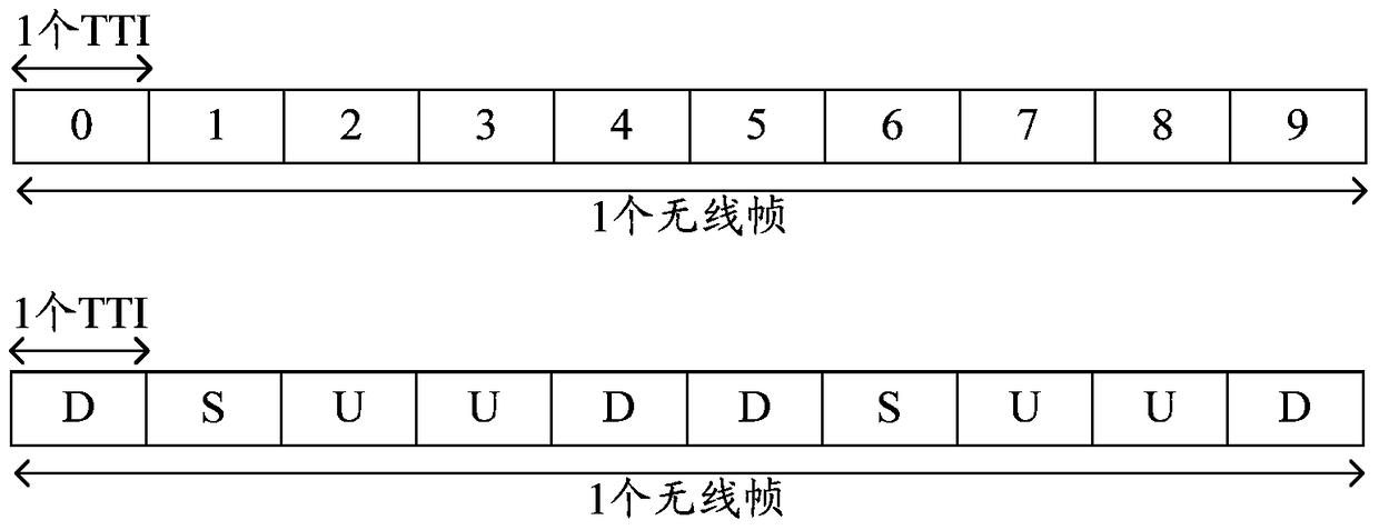
[0228] For example, the network device may configure the uplink and downlink subframe configuration of a radio frame to the user equipment through broadcast signaling. For example, in the uplink and downlink subframe configuration indicated by the network equipment through broadcast signaling, the TTI numbered i can be used to transmit downlink signals, and the TTI numbered i+1 can be used to transmit uplink signals. For another example, the TTI numbered i can be used to transmit physical broadcast signals. Figure 3A It is a schematic diagram of the subframe configuration of a radio frame according to an embodiment of the present invention.
[0229] See Figure 3A In the LTE system, a radio frame can include 10 TTIs. In each radio frame, the subframe that is completely used for downlink transmission is marked as D, the subframe that is completely used for uplink transmission is marked as U, and some of them are used for Downlink transmission, part of the subframe used for uplink transmission is marked as S. In addition, in the LTE system, the network device may send broadcast signaling to the user equipment to configure the ratio of uplink and downlink subframes. For example, in a configuration ratio, subframes numbered 3 and 8 are used for uplink transmission. In the case of not using the embodiment of the present invention, the user equipment in all the time periods used for uplink transmission (for example, the TTI numbered 2), according to figure 1 The shown uplink subcarrier-frequency mapping method maps the uplink signal to the first frequency corresponding to the multiple subcarriers, and sends the uplink signal on the first frequency, and in all the time periods used for downlink transmission (for example, the number 4 In TTI), the downlink signal is obtained from the second frequency corresponding to the multiple subcarriers according to the downlink subcarrier-frequency mapping mode. The network equipment can send broadcast signaling to the user equipment to indicate the uplink and downlink subframe configuration of a radio frame: for example, the subframes numbered 1 and 6 can be used to transmit downlink signals, and the first subframe thereafter can be used to transmit uplink Signal, that is, the subframes numbered 1 and 6 are S subframes; since S subframes are very important in Time Domain Duplex (TDD) systems, such TTIs can be used as the second period of the present invention. To avoid causing strong interference to the signal in the TTI, in this way, part or all of the subframes in a radio frame except the subframe numbered S can use the solution of the embodiment of the present invention. Alternatively, the TTIs numbered 0 and 5 can be used to transmit physical broadcast signals. For example, if the LTE system transmits signals on a physical broadcast channel (Physical Broadcast CHannel, PBCH), these two TTIs do not use the present invention. In this way, the solution of the embodiment can avoid causing interference to very important physical broadcast signals.
[0230] According to the embodiment of the present invention, the system bandwidth shared by the first subcarrier and the second subcarrier includes multiple subcarriers, half of which are high frequency subcarriers, and the other half are low frequency subcarriers; in the second time period , The second sub-carrier is a subset of high-frequency sub-carriers or low-frequency sub-carriers.
[0231] For example, in the second period, the network device schedules the signal sent or received by the user equipment to occupy only the high frequency band of the system bandwidth (such as figure 1 As shown in the upper part of the figure 1 (Shown in the lower half) of the bandwidth.
[0232] According to the embodiment of the present invention, the first signal and the second signal are respectively sent on the frequency corresponding to the continuous subcarrier.
[0233] In other words, network equipment can schedule user equipment to use figure 1 The system bandwidth is a subset of the low-band bandwidth or the high-band bandwidth to send or receive signals. The transmission scheduled by the network device cannot cross the frequency point f_0, which facilitates the reuse of the original module by the user equipment using the embodiment of the present invention. For example, the signal sent by the user equipment uses figure 1 The continuous subcarrier mapping method in A) will not reserve a subcarrier in the middle of the system bandwidth. In the second time period, the network equipment schedules the signal sent or received by the user equipment to be mapped to the frequency corresponding to the continuous subcarrier. If the embodiment of the present invention is used and used in the second time period, figure 1 The sub-carrier-frequency mapping method in B) can also keep the sub-carriers continuous without reserving a sub-carrier in the middle of the system bandwidth. That is, the user equipment is only mapped in the low frequency band or the system bandwidth in the second period. On the frequency corresponding to the continuous sub-carriers of the high frequency band, the module that maps the signal to the continuous sub-carriers in the existing user equipment can be reused, thereby reducing the complexity of upgrading the existing user equipment .
[0234] According to an embodiment of the present invention, the first signal is an OFDMA signal and the second signal is an SC-FDMA signal; or, the second signal is an OFDMA signal, and the first signal is an SC-FDMA signal.
[0235] For example, the network device generates an OFDMA signal and transmits it in the first period, generates an SC-FDMA signal and transmits it in the second period, and the user equipment also generates and transmits an SC-FDMA signal in the second period; or, the user equipment in the first period The SC-FDMA signal is generated and sent, the OFDMA signal is generated and sent in the second period, and the network device also generates the OFDMA signal and sent in the second period. In this way, the user equipment and the network equipment use the same generation method to generate signals in the second time period, which is convenient to reduce the mutual ICI of the signals sent by the user equipment and the network equipment at the same time. When such a method is applied to the LTE system, backward compatibility with the LTE system can also be maintained, that is, the user equipment of the lower version (for example, using the existing technology) can use the conventional method in the first period and the third period Communication, and a user equipment of a higher version (for example using the present invention) can also use the embodiments of the present invention in the first time period and the second time period.
[0236] According to the embodiment of the present invention, the first device is the first user equipment. In 220, the first user equipment sends a second signal to the first network device in the second time period, where the second subcarrier-frequency mapping method is the same as that of the first user equipment. The subcarrier-frequency mapping manner used by the network device to receive the signal sent by the second network device in the second time period is the same.
[0237] For example, the first user equipment may determine, according to the first subcarrier-frequency mapping manner, the first frequency corresponding to the first subcarrier used to map the uplink signal in the TTI numbered 2, and the first frequency on the first frequency A network device sends an uplink signal, determines the second frequency corresponding to the second subcarrier used to send the uplink signal in the TTI numbered 4 according to the second subcarrier-frequency mapping mode, and sends the uplink signal on the second frequency. At the same time, the second network-side device can use the second subcarrier-frequency mapping method to send signals in the second period, that is, the second subcarrier-frequency mapping method used by the first user equipment and the second network device send signals in the second period The sub-carrier-frequency mapping method used is the same. Since the first network device can use the same subcarrier-frequency mapping method to receive the signals sent by the first user equipment and the second network device, the first user equipment and the second network can be removed by means of resource scheduling or interference cancellation. Interference between signals sent by devices.
[0238] Specifically, in a scenario where different network devices use the same TTI for uplink or downlink transmission, or in a wireless backhaul (Wireless Backhaul) scenario, in the same time period, the user equipment and the network device can use the same subcarrier -Signals are sent in frequency mapping mode, and other network devices can use the same subcarrier-frequency mapping mode to receive signals sent by the user equipment and the network device, so that the user equipment and the network device can be removed by means of resource scheduling or interference cancellation. Interference between signals sent by the network device, among which the transmission between other network devices and the network device is called backhaul transmission; and other network devices use the same system bandwidth and time period as the user device to receive the network device transmission The signal is usually called in-band wireless backhaul transmission.
[0239] According to the embodiment of the present invention, the first device is the first user equipment, and the first signal and the second signal are both reference signals. In 220, the first user equipment can use the reference signal used by the second network device to send the reference signal. The reference signal resources with different signal resources send the second signal to the first network device.
[0240] Since the first network device can receive the reference signals sent by the first user equipment and the second network device on different reference signal resources, interference between the signals sent by the first user equipment and the second network device can be avoided.
[0241] According to the embodiment of the present invention, the reference signal resource corresponding to the second subcarrier or the second signal is pre-configured. For example, the pre-configuration can be performed by the first network device, the second network device, or any other network device.
[0242] If the first device is the first user equipment, then in 220, the first user equipment can use the resources pre-configured by the network device to send the second signal. If the first device is the first network device, then in 220, the first network device The device may use resources pre-configured by other network devices to send the second signal, where the pre-configured resources include time resources or frequency resources or reference signal resources.
[0243] According to the embodiment of the present invention, the first device is the first user equipment. In 220, the first user equipment sends a second signal to the second user equipment, where the second subcarrier-frequency mapping method is in the same manner as the second user equipment. The subcarrier-frequency mapping manner used for receiving the downlink signal sent by the third network device in the second time period is the same.
[0244] For example, the first user equipment and the second user equipment are devices that support device to device (Device to Device, D2D) transmission. The first user equipment and the third network equipment may use the same subcarrier-frequency mapping method to send signals in the same subframe, and the second user equipment may use the same subcarrier-frequency mapping method to receive the user equipment and the third network The signal sent by the device (the transmission between the first user equipment and the second user equipment is called D2D transmission), so that resource scheduling or interference cancellation can be used to remove one of the signals sent by the first user equipment and the third network device. Interference between.
[0245] According to the embodiment of the present invention, the first signal and the second signal are both reference signals, and the first user equipment may use a reference signal resource different from the reference signal resource used by the third network device to send the reference signal to the second user equipment The second signal, where the reference signal resource used by the first user equipment is configured by the third network device.
[0246] Since the second user equipment can receive the reference signals sent by the first user equipment and the third network equipment on different reference signal resources, interference between the signals sent by the first user equipment and the third network equipment can be avoided.
[0247] According to the embodiment of the present invention, before the first device determines the second frequency corresponding to the second subcarrier used for mapping the second signal in the second time period according to the second subcarrier-frequency mapping manner, figure 2 The method further includes: the first device receives configuration signaling for configuring the second time period.
[0248] If the first device is the first user equipment, the configuration signaling may be sent by the first network device. If the first device is the first network device, the configuration signaling may be sent by the second network device.
[0249] For example, the second period may be periodic, and the network device responsible for configuring the second period may determine or select the second period, and send semi-static signaling to the user equipment to configure the period and/or time offset of the second period. For example, if the period of the second time period is fixed at 10 TTIs, the network device only needs to send the time offset of the second time period to the user equipment. For example, if the time offset is 3 TTIs, the second period is TTIs numbered 3, 13, 23....
[0250] According to the embodiment of the present invention, the first device receives the configuration signaling used to configure the second time period through the physical downlink control channel.
[0251] For example, the configuration signaling may be dynamic signaling carried in the PDCCH, so that the network device dynamically sets a certain TTI as the second TTI according to service conditions.
[0252] According to an embodiment of the present invention, the configuration signaling may be dedicated signaling for the first device.
[0253] For example, when the first device is a user equipment, the configuration signaling may be unique to the user equipment, that is, the network device sends the signaling to each user equipment to notify the configuration of the second TTI. Since the network equipment can send different configuration signaling to different user equipments, a certain TTI is indicated as the second TTI for those user equipments that need to use the embodiments of the present invention, and the TTI is indicated as the first TTI for other user equipments. Or the third TTI to reduce the complexity of other user equipment.
[0254] Optionally, as another embodiment, figure 2 The method further includes: the user equipment sends type indication information to the network device, so that the network device determines whether the first device executes according to the type indication information figure 2 Methods.
[0255] Specifically, the type indication information may include identification information of the interference cancellation capability of the user equipment or system version information supported by the user equipment.
[0256] For example, since the user equipment may not have the interference cancellation capability, the network device needs to determine whether the user equipment has the interference cancellation capability before sending the channel type indication information to the user equipment. Specifically, the user equipment can be used to indicate the user equipment. Whether the device has the interference cancellation capability identification information of the interference cancellation capability or judged according to the system information supported by the user equipment reported by the first terminal, the identification information may be the version information of the system. For example, when the system supported by the user equipment is only LTE R12, it is determined that the user equipment does not have the ability to perform interference cancellation operations on uplink and downlink signals, and therefore it is not suitable to use the method in the embodiment of the present invention. When the operating system of the user equipment supports LTE R13, it is determined that the user equipment has the ability to perform interference cancellation operations on uplink and downlink signals, so that the method of the embodiment of the present invention can be used to produce the aforementioned beneficial effects.
[0257] Optionally, as another embodiment, figure 2 The method may further include: the first device is user equipment, figure 2 The method further includes: the user equipment receives the mode configuration information sent by the network equipment, and the mode configuration information is used to configure the user equipment to execute figure 2 Methods.
[0258] In other words, the mode configuration information is used to configure the user equipment to use the method of the embodiment of the present invention. The network equipment can directly configure the user equipment so that the user equipment enters the transmission mode based on the time-varying subcarrier-frequency mapping method described in the embodiment of the present invention, which is convenient for the network equipment to instruct the user equipment to use according to the traffic load and interference conditions The method of the embodiment of the present invention.
[0259] Optionally, as another embodiment, the first device is user equipment, figure 2 The method may further include: the user equipment receives a cell notification sent by the network device in a broadcast mode, and the cell notification is used to notify the user equipment in the cell corresponding to the network device to be able to perform figure 2 Methods.
[0260] In other words, the network device notifies the user equipment of the support of the embodiment of the present invention in the cell where the user equipment is located by broadcasting. For example, the network device notifies the user equipment to use the method of the embodiment of the present invention in the PBCH signal, so that the user equipment can use the method of the embodiment of the present invention to send or receive according to the information and using, for example, the mode configuration information described above. .
[0261] The embodiments of the present invention can be applied to a flexible duplex system. Through the embodiments of the present invention, shared resources can be used for uplink and downlink signals, instead of allocating relatively fixed and different resources (different frequency domain resources or different time domains) for uplink and downlink signals like traditional FDD or TDD systems. Resources), which can well support flexible duplex systems.
[0262] Figure 4 It is a schematic flowchart of a signal transmission method according to another embodiment of the present invention. Figure 4 The method is executed by user equipment or network equipment. Figure 4 Example of and figure 2 Corresponding to the embodiments, detailed descriptions are appropriately omitted here.
[0263] 410. The first device determines the first frequency corresponding to the first subcarrier used for receiving the first signal in the first period according to the first subcarrier-frequency mapping manner, and receives the first signal on the first frequency.
[0264] 420. The first device determines the second frequency corresponding to the second subcarrier used to receive the second signal in the second time period according to the second subcarrier-frequency mapping method, and receives the second signal on the second frequency; wherein, The first subcarrier-frequency mapping method is different from the second subcarrier-frequency mapping method, and the first frequency and the second frequency belong to the same frequency band.
[0265] According to an embodiment of the present invention, the first device may receive the first signal in the first subcarrier-frequency mapping manner in the first period, and receive the second signal in the second subcarrier-frequency mapping manner in the second period. Since the first device can use different (e.g., uplink and downlink) subcarrier-frequency mapping methods to receive signals in different time periods, the first device (e.g., user equipment or network equipment) can flexibly operate in the required time period Performing uplink transmission or downlink transmission improves the transmission performance of the system and improves the efficiency of frequency band usage.
[0266] According to the embodiment of the present invention, Figure 4 The method further includes: the first device determines the third frequency corresponding to the third subcarrier used for mapping the third signal in the third time period according to the second subcarrier-frequency mapping manner, and sends the third signal on the third frequency .
[0267] According to the embodiment of the present invention, the first frequency is a subset of the first frequency set corresponding to the first subcarrier-frequency mapping method, and the second frequency is the subset of the second frequency set corresponding to the second subcarrier-frequency mapping method. A subset, where the first frequency set does not have any overlap with the second frequency set.
[0268] According to the embodiment of the present invention, the first signal and the second signal are both reference signals, Figure 4 The method further includes: the first device determines the first resource unit corresponding to the first signal in the first period according to the first reference signal-resource unit mapping mode, and determines that the first resource unit corresponds to the first signal in the second period according to the second reference signal-resource unit mapping mode A second resource unit corresponding to the second signal; after the first device receives the first signal on the first frequency, Figure 4 The method further includes: the first device obtains the first signal from the first resource unit, and after the first device receives the second signal on the second frequency, Figure 4 The method further includes: the first device obtains the second signal from the second resource unit; wherein, any resource unit is uniquely determined by a symbol in the time domain and a subcarrier in the frequency domain.
[0269] According to the embodiment of the present invention, Figure 4 The method further includes: before sending the third signal on the third frequency, the first device may determine the third resource unit corresponding to the third signal in the third period according to the first reference signal-resource unit mapping mode, and combine the third The signal is mapped on the third resource unit.
[0270] According to the embodiment of the present invention, the first signal and the second signal are both control signals; wherein after receiving the first signal on the first frequency, Figure 4 The method further includes: acquiring the first control signal from the determined subcarrier corresponding to the first resource, where after receiving the second signal on the second frequency, Figure 4 The method further includes: acquiring a second control signal from a subcarrier corresponding to the determined second resource, where the first resource and the second resource are time-frequency resources or orthogonal code resources, and the first resource is different from the second resource.
[0271] According to an embodiment of the present invention, in 410, the first signal can be received according to the first power, and in 420, the second signal can be received according to the second power, where there is a power deviation between the first power and the second power, The power deviation is preset, or the power deviation is notified to the first device by signaling.
[0272] According to an embodiment of the present invention, the second power is higher than the first power. For example, the power deviation is a positive decibel dB value.
[0273] According to an embodiment of the present invention, the second period includes at least one orthogonal frequency division multiple access OFDMA symbol or at least one single carrier frequency division multiple access SC-FDMA symbol or at least one transmission time interval TTI.
[0274] According to an embodiment of the present invention, when the second time period includes at least one TTI, the second time period includes TTIs other than the TTI for transmitting the physical broadcast signal and the switching TTI from downlink transmission to uplink transmission.
[0275] According to the embodiment of the present invention, the system bandwidth shared by the first subcarrier and the second subcarrier includes multiple subcarriers, half of which are high frequency subcarriers and the other half are low frequency subcarriers; in the second time period , The second sub-carrier is a subset of high-frequency sub-carriers or low-frequency sub-carriers.
[0276] According to the embodiment of the present invention, the first signal and the second signal are respectively received on frequencies corresponding to consecutive subcarriers.
[0277] According to an embodiment of the present invention, the first signal is an OFDMA signal and the second signal is an SC-FDMA signal; or, the second signal is an OFDMA signal, and the first signal is an SC-FDMA signal.
[0278] According to the embodiment of the present invention, the first device is the first network device, and in 420, the first network device receives the second signal sent by the first user equipment, and the second subcarrier-frequency mapping method is the same as that of the first network device. The subcarrier-frequency mapping manner used for receiving the signal sent by the second network device in the second time period is the same.
[0279] According to the embodiment of the present invention, the first device is the first network device, and the first signal and the second signal are both reference signals. In 420, the first network device can use the reference signal used by the second network device to send the reference signal. The reference signal resources with different signal resources receive the second signal sent by the first user equipment.
[0280] According to the embodiment of the present invention, in 420, the reference signal resource corresponding to the second subcarrier or the second signal is pre-configured.
[0281] According to the embodiment of the present invention, the first device is the second user equipment. In 420, the second user equipment can receive the second signal sent by the first user equipment, and the second subcarrier-frequency mapping method is the same as that of the second user equipment. The subcarrier-frequency mapping manner used for receiving the downlink signal sent by the third network device in the second period is the same.
[0282] According to the embodiment of the present invention, the first signal and the second signal are both reference signals. In 420, the second user equipment may use a reference signal resource that is different from the reference signal resource used by the third network device to send the reference signal to receive the second signal. 2. The second signal sent by the user equipment, where the reference signal resource used by the second user equipment is configured by the third network device.
[0283] According to the embodiment of the present invention, before the first device determines the second frequency corresponding to the second subcarrier used to receive the second signal in the second period according to the second subcarrier-frequency mapping manner, the second Figure 4 The method further includes: the first device sends configuration signaling for configuring the second time period.
[0284] According to the embodiment of the present invention, the first device may send configuration signaling for configuring the second time period to the user equipment through the physical downlink control channel.
[0285] According to the embodiment of the present invention, the configuration signaling is dedicated signaling for the first device.
[0286] Optionally, as another embodiment, Figure 4 The method also includes: Figure 4 The method further includes: the first device determines the fourth frequency corresponding to the fourth subcarrier used to receive the fourth signal in the second time period according to the second subcarrier-frequency mapping manner, and receives the fourth signal on the fourth frequency , Where the resources used by the first device to receive the fourth signal are the same as those used to receive the second signal; the first device performs multiple input multiple output (MIMO) reception processing on the second signal and the fourth signal, or Multiple User-MIMO (MU-MIMO) MU-MIMO reception processing or interference cancellation.
[0287] For example, in LTE, a physical resource block (PRB) pair (PRB pair) includes a TTI in time and 12 sub-carriers in frequency, while network equipment performs uplink transmission (such as PUSCH) or downlink transmission ( For example, PDSCH) is usually scheduled in units of PRB pairs. For example, the first device is the first network device, and when the interference cancellation method is used to reduce the interference between these signals, in the same TTI (for example, the second TTI in this embodiment), the first network The device can allocate PRB pairs numbered 1 to 3 to the first user equipment using the embodiment of the present invention, and instruct it to use the downlink subcarrier-frequency mapping method to transmit signals, and the second network device also uses the number PRB pairs 1 to 3 use downlink subcarrier-frequency mapping to send signals (for example, to another user equipment). At this time, the signal sent by the second network device will cause interference to the signal sent by the first user equipment; Since the second network device and the first user equipment both use the same subcarrier-frequency mapping method to send signals, the first network device can first demodulate the signal sent by the second network device, and then re-transmit the signal according to the demodulation result. Generate an interference signal, subtract the regenerated interference signal from the received signal to obtain a signal with reduced interference and perform further receiving processing, thereby enhancing the first network device's ability to receive the signal sent by the first user equipment . Specifically, for example, the signals sent by the first user equipment and the second network equipment are S1 and S2 respectively, and the channel fading experienced by these two signals when they reach the first network equipment is H1 and H2 respectively, then the first network equipment receives The signal is R=S1×H1+S2×H2+n, where n represents noise. The first network device can first estimate the channel fading H2 experienced by the signal sent by the second network device ~ (Estimated channel fading), and then demodulate to determine that the transmitted signal is S2 ~ (Demodulate the signal sent by the second network device); then you can reconstruct the signal S2 received from the second network device ~ ×H2 ~ , And finally subtract S2 from the received signal R ~ ×H2 ~ In this way, the signal sent by the first user equipment with reduced interference can be obtained, so that the reception performance of the signal sent by the first user equipment by the first network device can be enhanced. In the conventional LTE system, since the uplink signal sent by the first user equipment and the downlink signal sent by the second network device use a frequency misaligned subcarrier-frequency mapping method, there is inter-carrier interference between the two signals, and interference cannot be used. Delete method to reduce interference.
[0288] It should be noted that, in the foregoing embodiment, the same resource includes the same resource or the same resource part. The embodiment with the same resource is given above. For example, the first user equipment and the second network device are both numbered 1~ 3 PRB pairs are used to send signals. In fact, the embodiments of the present invention are also applicable to situations where the resource parts are the same. For example, the first user equipment uses PRB pairs numbered 1 to 3 to send signals, while the second network device uses The PRB pairs numbered 3-6 send signals, and the method of the embodiment of the present invention can also be used to reduce interference, for example, the interference cancellation method is used for the signal sent on the PRB pair numbered 3. The following description is similar and will not be repeated hereafter.
[0289] Optionally, as another embodiment, Figure 4 The method further includes: the first device determines the fourth frequency corresponding to the fourth subcarrier used to receive the fourth signal in the second time period according to the second subcarrier-frequency mapping manner, and receives the fourth signal on the fourth frequency , Wherein the resource used by the first device for receiving the fourth signal is different from the resource used for receiving the second signal.
[0290] In other words, the embodiment of the present invention can use the scheduling method to reduce the interference between these signals. For example, in the embodiment of the present invention, the first device is a network device. In the same TTI (second TTI), the network device may, for example, allocate PRB pairs numbered 1 to 3 to the embodiment using the present invention. And instruct it to use the downlink subcarrier-frequency mapping method to send signals (uplink signals), and send signals (downlink signals) to other user equipment on PRB pairs numbered 4-6; The signal and the signal sent by the network device use the same subcarrier-frequency mapping method and send signals on different PRB pairs, so there is no interference between each other. In this way, the signal sent by the user equipment using the embodiment of the present invention is different. It will interfere with other user equipment receiving the signal sent by the network equipment. In the conventional LTE system, due to the particularity of multi-carrier signals, it is not feasible to reduce interference in this way. Because of the sub-carrier misalignment between the uplink signal and the downlink signal, it will cause inter-carrier interference (even if allocated Different PRB pairs are also difficult to eliminate the interference).
[0291] Optionally, as another embodiment, the first device is a network device, Figure 4 The method further includes: the network device receives the type indication information sent by the user equipment; the network device determines that the user equipment executes according to the type indication information figure 2 Methods.
[0292] According to an embodiment of the present invention, the type indication information includes identification information of the interference cancellation capability of the user equipment or system version information supported by the user equipment.
[0293] Optionally, as another embodiment, the first device is a network device, and the method further includes: the network device sends mode configuration information to the user equipment for configuring the user equipment to execute figure 2 Methods.
[0294] Optionally, as another embodiment, the first device is a network device, Figure 4 The method further includes: the network device sends a cell notification by broadcasting, and the cell notification is used to notify the user equipment in the cell corresponding to the network device to be able to perform figure 2 Methods.
[0295] Figure 5 It is a schematic flowchart of a signal transmission method according to another embodiment of the present invention. Figure 5 The method is executed by network equipment (for example, base station). The network equipment as the control node can schedule user equipment and other network equipment to perform and figure 2 The method is similar to the embodiment, and detailed description is appropriately omitted here.
[0296] 510. The first network device schedules the first user equipment so that the first user equipment determines the first frequency corresponding to the first subcarrier used for mapping the first signal in the first time period according to the first subcarrier-frequency mapping manner, and The first user equipment is caused to transmit the first signal on the first frequency.
[0297] 520. The first network device schedules the second network device so that the second network device determines the second frequency corresponding to the second subcarrier used for mapping the second signal in the first time period according to the first subcarrier-frequency mapping manner, and The second network device is caused to send the second signal on the second frequency.
[0298] According to the embodiment of the present invention, the first network device can schedule the first device and the second network device to use the same subcarrier-frequency mapping method to transmit signals in the same time period, thereby improving the flexibility of uplink and downlink transmission and improving the system The transmission performance, and improve the efficiency of the frequency band. In addition, because the same subcarrier-frequency mapping method is used to transmit signals during uplink transmission or downlink transmission in a subframe, the receiving end can reduce reception in this subframe by scheduling or interference cancellation. Interference between incoming signals.
[0299] Optionally, as another embodiment, the first network device may also schedule the first user equipment so that the first user equipment determines the third signal for mapping the third signal in the second time period according to the second subcarrier-frequency mapping manner. The third frequency corresponding to the subcarrier, and enables the first user equipment to send the third signal on the third frequency.
[0300] Optionally, as another embodiment, the first network device may also schedule the first user equipment so that the first user equipment determines the fourth signal for receiving the fourth signal in the third period according to the first subcarrier-frequency mapping manner. The fourth frequency corresponding to the sub-carrier, and the fourth signal is received on the fourth frequency.
[0301] The first frequency is a subset of the first frequency set corresponding to the first subcarrier-frequency mapping method, and the second frequency is the subset of the second frequency set corresponding to the second subcarrier-frequency mapping method, where the first The frequency set does not have any overlap with the second frequency set.
[0302] Optionally, as another embodiment, the first network device receives the first signal and the second signal, and performs multiple-input multiple-output MIMO reception processing on the first signal and the second signal or multi-user-multiple-input multiple-output MU- MIMO reception processing or interference cancellation, where the first user equipment and the second network equipment are scheduled to have the same resources; or, the first network equipment receives the first signal and the second signal, where the first user equipment and the second network equipment are scheduled The resources are different.
[0303] According to the embodiment of the present invention, the first network device schedules the second user equipment so that the second user equipment receives the first signal and the second signal, and performs multiple-input multiple-output MIMO reception processing on the first signal and the second signal. User-multiple-input multiple-output MU-MIMO reception processing or interference cancellation, where the first user equipment and the second network equipment are scheduled to be the same; or, the first network equipment schedules the second user equipment so that the second user equipment receives the second user equipment The first signal and the second signal, wherein the first user equipment and the second network equipment have different scheduled resources.
[0304] Image 6 It is a schematic flowchart of a signal transmission scenario according to an embodiment of the present invention. Image 6 The example is figure 2 Examples of methods.
[0305] In dynamic TDD (that is, the configuration ratio of TDD uplink and downlink subframes can be dynamically changed, and the configuration ratio of uplink and downlink subframes of different network devices is different, which causes different network devices to regard the same TTI as different uplink time periods/downlink time periods) scenarios Next, the first user equipment and the second network equipment use the same downlink subcarrier-frequency mapping method to send signals, that is, the first network equipment uses the same subcarrier-frequency mapping method to simultaneously receive the first user equipment and the second network The signal sent by the device (the signal sent by the second network device is interference to the signal sent by the first user equipment). The signal sent by the second network device may cause interference to the first network device to receive the uplink signal sent by the first user equipment. The first network device further instructs the first user equipment to use the same subcarrier-frequency mapping manner as the subcarrier-frequency mapping manner used by the second network device to send signals. In order to reduce interference, the second network device may send a resource occupation message to the first network device in advance to notify the first network device of the resources used by the second network device to send signals (resources include time, frequency, scrambling code or RS resources) Wait). After receiving the resource occupation message, the first network device schedules resources for the first user equipment, and the resources overlap with the resources used by the second network device to send signals. After the first network device receives the signals sent by the first user equipment and the second network device, it can reduce the interference caused by the signal sent by the second network device on the reception of the first network device by means of interference cancellation, and enhance the interference to the first user The reception performance of the signal sent by the device. The embodiment in which the first network device schedules the second network device and the first user equipment to use non-overlapping resources is the same as the previous description, and will not be repeated here.
[0306] Since the first user equipment and the second network equipment use the same downlink subcarrier-frequency mapping method to transmit signals, the scheduling method or interference cancellation method can be used to reduce the signal sent by the second network equipment to the first user equipment. Signal interference, thereby enhancing the performance of the first network device to receive the signal sent by the first user equipment.
[0307] Furthermore, in this embodiment, a control node (not shown) can also be used to control or schedule the first network device and the second network device to send and receive signals, so that the second network device does not need to send resource occupation to the first network device in advance. Information, for example, the control node controls the second network device to send a downlink signal to the second user equipment, controls the first network device to schedule the same resource for the first user equipment to send the uplink signal, and uses the same subroutine used by the second network device to send The carrier-frequency mapping manner is the same sub-carrier-frequency mapping manner, and finally the first network device is controlled to perform an interference cancellation operation to enhance the reception performance of the uplink signal sent by the first user equipment.
[0308] Figure 7 It is a schematic flowchart of a signal transmission scenario according to another embodiment of the present invention. Figure 7 The example is figure 2 Examples of methods.
[0309] In the wireless backhaul scenario, the first network device and the first user equipment use the same frequency to send useful signals to the second network device at the same time, and the second network device simultaneously receives two signals and demodulates the two signal. In the conventional technology, the first network device sends a downlink signal, and the user equipment sends an uplink signal. Because the first network device and the first user equipment use different subcarrier-frequency mapping methods to send signals to the second network device, Therefore, there is inter-carrier interference between these two signals, which makes it difficult to remove the interference. Different from Image 6 In the scenario described, in this scenario, the first network device is, for example, a high-power node, the second network device is, for example, a low-power node, and the first network device has control capability over the second network device; the first network device In order to send information to the first user equipment, the signal can be sent to the second network equipment wirelessly (the transmission link of different network equipment is called backhaul), and then the second network equipment forwards it to the first user equipment . This scenario is similar to the Relay scenario (the base station first sends the signal to the relay, and then the relay sends the signal to the user equipment). The difference is that in order to avoid interference, the transmission between the base station and the relay needs to be occupied Reserved resources (for example, reserved TTIs or reserved frequency bands), which cannot be used to transmit other signals. In the present invention, the first network device and the user equipment can use the same time and frequency to send signals to the second network device, which helps to improve transmission efficiency. According to the embodiment of the present invention, the first network device and the first user equipment can send useful signals in the second TTI, and the two signals can be demodulated separately in the second network device through interference cancellation technology, or through MIMO The receiving algorithm or Multi-User Multiple Input and Multiple Output (MU-MIMO) receiving algorithm demodulates the two signals. In addition, a scheduling method can also be used to avoid interference, and the specific method is the same as the scheduling method described above, and will not be repeated here.
[0310] Figure 8 It is a schematic flowchart of a signal transmission scenario according to an embodiment of the present invention. Figure 8 The example is figure 2 Examples of methods.
[0311] In the transparent D2D scenario, the first user equipment can communicate with the network equipment in the TTI numbered 2 and 4 according to the conventional LTE method, and in the TTI numbered 3, send a signal to the first according to the downlink subcarrier-frequency mapping method. Second user equipment. The advantage of this is that even if the second user equipment is a user equipment that does not support D2D transmission (for example, a user equipment of a low version of LTE), it can still obtain D2D benefits through the solution of the embodiment of the present invention. Advantages, at this time, the signal sent by the first user equipment to the second user equipment uses the subcarrier-frequency mapping method of the downlink signal, and the second user equipment receives the signal sent by the first user equipment in the same way as the signal sent by the network device. signal of.
[0312] Further, the network device can also send signals to the second user equipment at the same time. Same as the above example, the second user equipment can use receiving algorithms such as interference cancellation or MIMO processing or multi-user multiple input multiple output processing to receive two signals. Improve transmission efficiency; or, the network device can also send signals to other user equipment at the same time, and the second user equipment can use the IC receiving algorithm to enhance the reception of signals sent by the first user equipment, because the signals sent by the first user equipment and the network equipment Both use the same sub-carrier-frequency mapping method for mapping, so the mutual interference between these signals can be reduced through the scheduling method or the interference cancellation method.
[0313] Picture 9 It is a schematic flowchart of a signal transmission scenario according to an embodiment of the present invention. Picture 9 The example is figure 2 Examples of methods.
[0314] In a full duplex (full duplex) scenario, the first user equipment can communicate with the network equipment in the TTI numbered 2 and 4 according to the conventional LTE method, and in the TTI numbered 3 according to the downlink subcarrier-frequency mapping method The signal is sent to the network device, and the network device simultaneously sends the signal to the second user equipment according to the downlink subcarrier-frequency mapping method. At this time, the network device uses the same frequency to send and receive simultaneously, thereby improving the transmission efficiency of the system. Similarly, if the network device knows the signal to be sent, it can reduce the interference of the signal sent to the second user equipment to the signal received from the first user equipment through a scheduling method or an interference cancellation method.
[0315] Picture 10 It is a schematic flowchart of a signal transmission scenario according to an embodiment of the present invention. Picture 10 The example is figure 2 Examples of methods.
[0316] In the scenario of mutual detection between network devices, the first user equipment uses the downlink subcarrier-frequency mapping method in the second TTI to send reference signals for measurement (for example, downlink CSI-RS or uplink SRS in the LTE system). , Are used to measure channel information). At the same time, the first network device can also send CSI-RS to the second network device or receive CSI-RS from the second network device. In this way, when the CSI-RS sent by the user equipment is The CSI-RS sent between the RS and the network device uses the same subcarrier-frequency mapping method and uses mutually orthogonal resources to avoid mutual interference. This method allows network devices to send reference signals to each other to detect the channel conditions between network devices. For example, if the first network device sends CSI-RS to the second network device, the second network device can use the received CSI -RS is used to obtain the channel condition between two network devices, and according to this information, learn the interference condition that the first network device may cause to the second network device or the channel condition between the two network devices. By using the present invention, the resources of uplink and downlink signals can be used more flexibly to improve transmission efficiency and avoid mutual interference between uplink and downlink reference signals used for measurement.
[0317] Figure 6 to Figure 10 The embodiment of is described by taking the embodiment of the present invention applied to user equipment as an example. It should be understood that Figure 6 to Figure 10 The above embodiments can also be applied to network equipment, which will not be repeated here.
[0318] Picture 11 It is a schematic structural block diagram of a signal transmission device 1100 according to an embodiment of the present invention. The device 1100 includes: a determining module 1110 and a sending module 1120.
[0319] The determining module 1110 is configured to determine the first frequency corresponding to the first subcarrier used to map the first signal in the first period according to the first subcarrier-frequency mapping mode, and determine the first frequency according to the second subcarrier-frequency mapping mode The two time periods are used to map the second frequency corresponding to the second subcarrier of the second signal. The sending module 1120 is configured to send a first signal on the first frequency determined by the determining module 1110, and send a second signal on the second frequency determined by the determining module 1110; wherein the first subcarrier-frequency mapping method is different from the second frequency. In the subcarrier-frequency mapping mode, the first frequency and the second frequency belong to the same frequency band.
[0320] According to the embodiment of the present invention, the first device may use the first subcarrier-frequency mapping method to transmit the first signal in the first period, and use the second subcarrier-frequency mapping method to transmit the second signal in the second period. Since the first device can use different (for example, uplink and downlink) subcarrier-frequency mapping methods to send signals in different time periods, the first device (for example, user equipment or network equipment) can flexibly be in the required time period Performing uplink transmission or downlink transmission improves the transmission performance of the system and improves the efficiency of frequency band usage.
[0321] Optionally, as another embodiment, the determining module 1110 is further configured to determine the third frequency corresponding to the third subcarrier used to receive the third signal in the third time period according to the second subcarrier-frequency mapping manner. The device 1100 further includes: a receiving module 1130. The receiving module 1130 is configured to receive the third signal at the third frequency determined by the determining module 1110.
[0322] According to the embodiment of the present invention, the first frequency is a subset of the first frequency set corresponding to the first subcarrier-frequency mapping method, and the second frequency is the subset of the second frequency set corresponding to the second subcarrier-frequency mapping method. A subset, where the first frequency set does not have any overlap with the second frequency set.
[0323] Optionally, as another embodiment, the first signal and the second signal are both reference signals; the determining module 1110 is further configured to determine the first signal corresponding to the first signal in the first period according to the first reference signal-resource unit mapping manner A resource unit, and the second resource unit corresponding to the second signal in the second time period is determined according to the second reference signal-resource unit mapping mode; wherein, any resource unit consists of a symbol in the time domain and a symbol in the frequency domain The subcarrier is uniquely determined; before sending the first signal, the sending module 1120 is also used to map the first signal on the first resource unit determined by the determining module; before sending the second signal, it is also used to map the second signal on The second resource unit determined by the determining module 1110.
[0324] Optionally, as another embodiment, the first signal and the second signal are both control signals; the determining module 1110 is further configured to determine the first resource and the second resource, where the first resource and the second resource are time-frequency resources Or orthogonal code resources, the first resource is different from the second resource; before sending the first signal, the sending module 1120 is also used to map the first signal to the subcarrier corresponding to the first resource determined by the determining module 1110; Before the second signal, it is also used to map the second signal to the subcarrier corresponding to the second resource determined by the determining module 1110.
[0325] According to the embodiment of the present invention, the sending module 1120 sends the first signal according to the first power and sends the second signal according to the second power, wherein there is a power deviation between the first power and the second power, and the power deviation is preset , Or the power deviation is notified to the device 1100 by signaling.
[0326] According to an embodiment of the present invention, the second power is higher than the first power.
[0327] According to an embodiment of the present invention, the second period includes at least one orthogonal frequency division multiple access OFDMA symbol or at least one single carrier frequency division multiple access SC-FDMA symbol or at least one transmission time interval TTI.
[0328] According to an embodiment of the present invention, when the second time period includes at least one TTI, the second time period includes TTIs other than the TTI for transmitting the physical broadcast signal and the switching TTI from downlink transmission to uplink transmission.
[0329] According to the embodiment of the present invention, the system bandwidth shared by the first subcarrier and the second subcarrier includes multiple subcarriers, half of which are high frequency subcarriers, and the other half are low frequency subcarriers; in the second time period , The second sub-carrier is a subset of high-frequency sub-carriers or low-frequency sub-carriers.
[0330] According to the embodiment of the present invention, the sending module 1120 respectively sends the first signal and the second signal on the frequency corresponding to the consecutive subcarriers.
[0331] According to an embodiment of the present invention, the first signal is an OFDMA signal and the second signal is an SC-FDMA signal; or, the second signal is an OFDMA signal, and the first signal is an SC-FDMA signal.
[0332] According to the embodiment of the present invention, the device 1100 is a first user equipment, and the sending module 1120 sends a second signal to the first network device, wherein the second subcarrier-frequency mapping method is the same as that of the first network device receiving the second network device in the second time period. The subcarrier-frequency mapping method used by the signal sent by the device is the same.
[0333] According to the embodiment of the present invention, the device 1110 is a first user equipment, the first signal and the second signal are both reference signals, and the sending module 1120 uses a reference signal resource different from the reference signal resource used by the second network device to send the reference signal Send a second signal to the first network device.
[0334] According to the embodiment of the present invention, the reference signal resource corresponding to the second subcarrier or the second signal is pre-configured.
[0335] According to the embodiment of the present invention, the device 1100 is the first user equipment, and the sending module 1120 sends the second signal to the second user equipment, wherein the second subcarrier-frequency mapping method is the same as that of the second user equipment receiving the third network in the second time period. The downlink signal sent by the device uses the same subcarrier-frequency mapping method.
[0336] According to the embodiment of the present invention, the first signal and the second signal are both reference signals, and the sending module 1120 uses a reference signal resource different from the reference signal resource used by the third network device to send the reference signal to the second user equipment. Signal, where the reference signal resource used by the sending module 1120 is configured by the third network device.
[0337] Optionally, as another embodiment, the device 1110 further includes: a receiving module 1130. The receiving module 1130 is configured to receive the second frequency for configuring the second time period before the determining module 1110 determines the second frequency corresponding to the second subcarrier used for mapping the second signal in the second time period according to the second subcarrier-frequency mapping manner. Configure signaling.
[0338] According to the embodiment of the present invention, the configuration signaling is Picture 11 Equipment-specific signaling.
[0339] Optionally, as another embodiment, the device 1100 is a user equipment, and the sending module 1120 is further configured to send type indication information to the network device, so that the network device can determine whether the device 1100 executes according to the type indication information. figure 2 Methods.
[0340] According to the embodiment of the present invention, the type indication information includes identification information of the interference cancellation capability of the user equipment or system version information supported by the user equipment.
[0341] Optionally, as another embodiment, the device 1100 is user equipment, and the user equipment further includes a receiving module 1130. The receiving module 1130 is used to receive the mode configuration information sent by the network equipment, and the mode configuration information is used to configure the user equipment to execute figure 2 Methods.
[0342] Optionally, as another embodiment, the device 1100 is user equipment, and the user equipment further includes a receiving module 1130. The receiving module 1130 block is used to receive the cell notification sent by the network device by broadcasting. The cell notification is used to notify the user equipment in the cell corresponding to the network device to be able to execute figure 2 Methods.
[0343] According to the embodiment of the present invention, the device 1100 is a user equipment or a network device.
[0344] The operation and function of each unit of the device 1100 can refer to figure 2 In order to avoid repetition, the corresponding method embodiments will not be repeated here.
[0345] Picture 12 It is a schematic structural block diagram of a signal transmission device 1200 according to another embodiment of the present invention. The device 1200 includes: a determining module 1210 and a receiving module 1220.
[0346] The determining module 1210 is configured to determine the first frequency corresponding to the first subcarrier used to receive the first signal in the first period according to the first subcarrier-frequency mapping mode, and determine the first frequency according to the second subcarrier-frequency mapping mode The second period is used to receive the second frequency corresponding to the second subcarrier of the second signal. The receiving module 1220 is configured to receive the first signal on the first frequency determined by the determining module 1210, and receive the second signal on the second frequency determined by the determining module 1210; wherein the first subcarrier-frequency mapping method is different from the second frequency. In the subcarrier-frequency mapping mode, the first frequency and the second frequency belong to the same frequency band.
[0347] According to an embodiment of the present invention, the first device may receive the first signal in the first subcarrier-frequency mapping manner in the first period, and receive the second signal in the second subcarrier-frequency mapping manner in the second period. Since the first device can use different (e.g., uplink and downlink) subcarrier-frequency mapping methods to receive signals in different time periods, the first device (e.g., user equipment or network device) can flexibly operate in the required time period. Performing uplink transmission or downlink transmission improves the transmission performance of the system and improves the efficiency of frequency band usage.
[0348] Optionally, as another embodiment, the determining module 1210 is further configured to determine the third frequency corresponding to the third subcarrier used to map the third signal in the third period according to the second subcarrier-frequency mapping manner, and the device 1200 Also includes: a sending module 1230. The sending module 1230 is configured to send a third signal on the third frequency determined by the determining module 1210.
[0349] According to the embodiment of the present invention, the first frequency is a subset of the first frequency set corresponding to the first subcarrier-frequency mapping method, and the second frequency is the subset of the second frequency set corresponding to the second subcarrier-frequency mapping method. A subset, where the first frequency set does not have any overlap with the second frequency set.
[0350] Optionally, as another embodiment, the first signal and the second signal are both reference signals; the determining module 1210 is further configured to determine the first signal corresponding to the first signal in the first period according to the first reference signal-resource unit mapping manner. A resource unit, and the second resource unit corresponding to the second signal in the second time period is determined according to the second reference signal-resource unit mapping mode; wherein, any resource unit consists of a symbol in the time domain and a symbol in the frequency domain The subcarrier is uniquely determined; after receiving the first signal, the receiving module 1220 is also used to obtain the first signal from the first resource unit determined by the determining module 1210; after receiving the second signal, it is also used to obtain the first signal determined from the determining module 1210 The second signal is acquired on the second resource unit.
[0351] Optionally, as another embodiment, the first signal and the second signal are both control signals; the determining module 1210 is further configured to determine the first resource and the second resource; where the first resource and the second resource are time-frequency resources Or orthogonal code resources, the first resource is different from the second resource; after receiving the first signal, the receiving module 1220 is also used to obtain the first control signal from the subcarrier corresponding to the first resource determined by the determining module 1210; After the second signal, it is also used to obtain the second control signal from the subcarrier corresponding to the second resource determined by the determining module 1210.
[0352] According to the embodiment of the present invention, the receiving module 1220 receives the first signal according to the first power, and receives the second signal according to the second power, wherein there is a power deviation between the first power and the second power, and the power deviation is preset , Or the power deviation is notified to the device 1200 by signaling.
[0353] According to an embodiment of the present invention, in a sixth possible implementation manner, the second power is higher than the first power.
[0354] According to an embodiment of the present invention, the second period includes at least one orthogonal frequency division multiple access OFDMA symbol or at least one single carrier frequency division multiple access SC-FDMA symbol or at least one transmission time interval TTI.
[0355] According to an embodiment of the present invention, when the second time period includes at least one TTI, the second time period includes TTIs other than the TTI for transmitting the physical broadcast signal and the switching TTI from downlink transmission to uplink transmission.
[0356] According to the embodiment of the present invention, the system bandwidth shared by the first subcarrier and the second subcarrier includes multiple subcarriers, half of which are high frequency subcarriers, and the other half are low frequency subcarriers; in the second time period , The second sub-carrier is a subset of high-frequency sub-carriers or low-frequency sub-carriers.
[0357] According to the embodiment of the present invention, the receiving module 1220 respectively receives the first signal and the second signal on the frequency corresponding to the continuous subcarrier.
[0358] According to an embodiment of the present invention, the first signal is an OFDMA signal and the second signal is an SC-FDMA signal; or, the second signal is an OFDMA signal, and the first signal is an SC-FDMA signal.
[0359] According to the embodiment of the present invention, the device 1200 is a first network device, and the receiving module 1220 receives the second signal sent by the first user equipment, wherein the second subcarrier-frequency mapping method is the same as that of the first network device receiving the second signal in the second time period. The signal sent by the network device uses the same subcarrier-frequency mapping method.
[0360] According to the embodiment of the present invention, the device 1200 is a first network device, the first signal and the second signal are both reference signals, and the receiving module 1220 uses a reference signal resource different from the reference signal resource used by the second network device to send the reference signal Receive the second signal sent by the first user equipment.
[0361] According to the embodiment of the present invention, the reference signal resource corresponding to the second subcarrier or the second signal is pre-configured.
[0362] According to the embodiment of the present invention, the device 1200 is a second user equipment, and the receiving module 1220 receives the second signal sent by the first user equipment. The second subcarrier-frequency mapping method and the receiving module 1220 receive the third network in the second time period. The subcarrier-frequency mapping method used by the device to send downlink signals is the same.
[0363] According to the embodiment of the present invention, the first signal and the second signal are both reference signals, and the receiving module 1220 uses a reference signal resource different from the reference signal resource used by the third network device to send the reference signal to receive the first signal sent by the second user equipment. The second signal, where the reference signal resource used by the receiving module 1220 is configured by the third network device.
[0364] Optionally, as another embodiment, the device 1200 further includes: a sending module 1230, configured to determine the second subcarrier used to receive the second signal in the second time period according to the second subcarrier-frequency mapping manner in the determining module 1210 Before the corresponding second frequency, send configuration signaling for configuring the second time period.
[0365] Optionally, as another embodiment, the determining module 1210 is further configured to determine the fourth frequency corresponding to the fourth subcarrier used to receive the fourth signal in the second time period according to the second subcarrier-frequency mapping manner, and the receiving module 1220 is further configured to receive the fourth signal on the fourth frequency, where the resource used by the receiving module 1220 to receive the fourth signal is the same as the resource used to receive the second signal, and the device 1200 further includes: a processing module 1240 for correcting The second signal and the fourth signal are subjected to multiple-input multiple-output MIMO reception processing or multi-user-multiple-input multiple output MU-MIMO reception processing or interference cancellation.
[0366] Optionally, as another embodiment, the determining module 1210 is further configured to determine the fourth frequency corresponding to the fourth subcarrier used to receive the fourth signal in the second time period according to the second subcarrier-frequency mapping manner, and the receiving module 1220 is further configured to receive a fourth signal on a fourth frequency, where the resource used by the receiving module 1220 for receiving the fourth signal is different from the resource used for receiving the second signal.
[0367] According to the embodiment of the present invention, the sending module 1230 sends configuration signaling for configuring the second time period to the user equipment through the physical downlink control channel.
[0368] According to the embodiment of the present invention, the configuration signaling is Picture 12 Equipment-specific signaling.
[0369] Optionally, as another embodiment, the device 1200 is a network device, and the receiving module 1220 is further configured to receive type indication information sent by the user equipment; the determining module 1210 is further configured to determine that the user equipment executes according to the type indication information. figure 2 Methods.
[0370] According to an embodiment of the present invention, the type indication information includes identification information of the interference cancellation capability of the user equipment or system version information supported by the user equipment.
[0371] Optionally, as another embodiment, the device 1200 is a network device, and the device 1200 further includes: a sending module 1230. The sending module 1230 is used to send mode configuration information to the user equipment, and the mode configuration information is used to configure the user equipment to execute figure 2 Methods.
[0372] Optionally, as another embodiment, the device 1200 is a network device, and the network device further includes: a sending module 1230. The sending module 1230 is used to send a cell notification by broadcasting, and the cell notification is used to notify the user equipment in the cell corresponding to the network device to be able to execute figure 2 Methods.
[0373] According to the embodiment of the present invention, the device 1200 is a network device or a user equipment.
[0374] The operation and function of each unit of the equipment 1200 can refer to Figure 4 In order to avoid repetition, the corresponding method embodiments will not be repeated here.
[0375] Figure 13 It is a schematic structural block diagram of a signal transmission device 1300 according to another embodiment of the present invention. The device 1300 includes: a first scheduling module 1310 and a second scheduling module 1320.
[0376] The first scheduling module 1310 is configured to schedule the first user equipment so that the first user equipment determines the first frequency corresponding to the first subcarrier used for mapping the first signal in the first time period according to the first subcarrier-frequency mapping manner, And make the first user equipment send the first signal on the first frequency. The second scheduling module 1320 is configured to schedule a second network device so that the second network device determines the second frequency corresponding to the second subcarrier used for mapping the second signal in the first time period according to the first subcarrier-frequency mapping manner, And make the second network device send the second signal on the second frequency.
[0377] According to the embodiment of the present invention, the first network device can schedule the first device and the second network device to use the same subcarrier-frequency mapping method to transmit signals in the same time period, thereby improving the flexibility of uplink and downlink transmission and improving the system The transmission performance, and improve the efficiency of the frequency band. In addition, because the same subcarrier-frequency mapping method is used to transmit signals during uplink transmission or downlink transmission in a subframe, the receiving end can reduce the reception in this subframe by scheduling or interference cancellation. Interference between incoming signals.
[0378] Optionally, as another embodiment, the device 1300 further includes: a receiving module 1330, configured to receive the first signal and the second signal; if the resources scheduled for the first user equipment and the second network device are the same, the device further includes The processing module 1340 is configured to perform multiple-input multiple-output MIMO reception processing or multi-user-multiple-input multiple-output MU-MIMO reception processing or interference cancellation on the first signal and the second signal.
[0379] Optionally, as another embodiment, the device 1300 further includes: a third scheduling module 1350, configured to schedule the second user equipment so that the second user equipment receives the first signal and the second signal, and compares the first signal with the second user equipment. Two signals are subjected to multiple input multiple output MIMO reception processing or multiple user-multiple input multiple output MU-MIMO reception processing or interference cancellation, where the first user equipment and the second network equipment are scheduled to be the same resource; or, the fourth scheduling module 1360 , Used to schedule the second user equipment, so that the second user equipment receives the first signal and the second signal, where the resources scheduled for the first user equipment and the second network equipment are different.
[0380] The operation and function of each unit of the device 1300 can be referred to Figure 5 In order to avoid repetition, the corresponding method embodiments will not be repeated here.
[0381] Figure 14 It is a schematic structural block diagram of a signal transmission device 1400 according to another embodiment of the present invention. The device 1400 includes: a processor 1410, a transmitter 1420, a memory 1430, and a communication bus 1440.
[0382] The processor 1410 calls the code in the memory 1430 through the communication bus 1440 to determine the first frequency corresponding to the first subcarrier used to map the first signal in the first period according to the first subcarrier-frequency mapping method, and according to the The two-subcarrier-frequency mapping method determines the second frequency corresponding to the second subcarrier used for mapping the second signal in the second time period; the transmitter 1420 is configured to send the first signal on the first frequency determined by the processor 1410, And send the second signal on the second frequency determined by the processor 1410, where the first subcarrier-frequency mapping manner is different from the second subcarrier-frequency mapping manner, and the first frequency and the second frequency belong to the same frequency band.
[0383] According to the embodiment of the present invention, the first device may use the first subcarrier-frequency mapping method to transmit the first signal in the first period, and use the second subcarrier-frequency mapping method to transmit the second signal in the second period. Since the first device can use different (for example, uplink and downlink) subcarrier-frequency mapping methods to send signals in different time periods, the first device (for example, user equipment or network equipment) can flexibly be in the required time period Performing uplink transmission or downlink transmission improves the transmission performance of the system and improves the efficiency of frequency band usage.
[0384] Optionally, as another embodiment, the processor 1410 is further configured to determine a third frequency corresponding to the third subcarrier used for receiving the third signal in the third period according to the second subcarrier-frequency mapping manner. The device 1400 further includes a receiver 1450. The receiver 1450 is configured to receive a third signal at a third frequency determined by the processor 1410.
[0385] According to the embodiment of the present invention, the first frequency is a subset of the first frequency set corresponding to the first subcarrier-frequency mapping method, and the second frequency is the subset of the second frequency set corresponding to the second subcarrier-frequency mapping method. A subset, where the first frequency set does not have any overlap with the second frequency set.
[0386] Optionally, as another embodiment, the first signal and the second signal are both reference signals; the processor 1410 is further configured to determine the first signal corresponding to the first signal in the first period according to the first reference signal-resource unit mapping manner. A resource unit, and the second resource unit corresponding to the second signal in the second time period is determined according to the second reference signal-resource unit mapping mode; wherein, any resource unit consists of a symbol in the time domain and a symbol in the frequency domain The subcarrier is uniquely determined; before sending the first signal, the transmitter 1420 is also used to map the first signal on the first resource unit determined by the processor 1410; before sending the second signal, it is also used to map the second signal On the second resource unit determined by the processor 1410.
[0387] Optionally, as another embodiment, the first signal and the second signal are both control signals; the processor 1410 is further configured to determine the first resource and the second resource; where the first resource and the second resource are time-frequency resources Or orthogonal code resources, the first resource is different from the second resource; before sending the first signal, the transmitter 1420 is also used to map the first signal to the subcarrier corresponding to the first resource determined by the processor 1410; Before the second signal, it is also used to map the second signal to the subcarrier corresponding to the second resource determined by the processor 1410.
[0388] According to an embodiment of the present invention, the transmitter 1420 transmits the first signal according to the first power, and transmits the second signal according to the second power, wherein there is a power deviation between the first power and the second power, and the power deviation is preset , Or the power deviation is notified to the device 1400 by signaling.
[0389] According to an embodiment of the present invention, the second power is higher than the first power.
[0390] According to an embodiment of the present invention, the second period includes at least one orthogonal frequency division multiple access OFDMA symbol or at least one single carrier frequency division multiple access SC-FDMA symbol or at least one transmission time interval TTI.
[0391] According to an embodiment of the present invention, when the second time period includes at least one TTI, the second time period includes TTIs other than the TTI for transmitting the physical broadcast signal and the switching TTI from downlink transmission to uplink transmission.
[0392] According to the embodiment of the present invention, the system bandwidth shared by the first subcarrier and the second subcarrier includes multiple subcarriers, half of which are high frequency subcarriers and the other half are low frequency subcarriers; in the second time period , The second sub-carrier is a subset of high-frequency sub-carriers or low-frequency sub-carriers.
[0393] According to the embodiment of the present invention, the transmitter 1420 respectively transmits the first signal and the second signal on the frequency corresponding to the continuous subcarrier.
[0394] According to an embodiment of the present invention, the first signal is an OFDMA signal and the second signal is an SC-FDMA signal; or, the second signal is an OFDMA signal, and the first signal is an SC-FDMA signal.
[0395] According to the embodiment of the present invention, the device 1400 is the first user equipment, and the transmitter 1420 sends the second signal to the first network device. The second subcarrier-frequency mapping method is the same as that of the first network device receiving the second network device in the second time period. The subcarrier-frequency mapping method used by the signal sent by the device is the same.
[0396] According to the embodiment of the present invention, the device 1400 is a first user equipment, the first signal and the second signal are both reference signals, and the transmitter 1420 uses a reference signal resource different from the reference signal resource used by the second network device to send the reference signal Send a second signal to the first network device.
[0397] According to the embodiment of the present invention, the reference signal resource corresponding to the second subcarrier or the second signal is pre-configured.
[0398] According to the embodiment of the present invention, the first device is a user equipment, the device 1400 is a first user equipment, and the transmitter 1420 sends a second signal to the second user equipment, where the second subcarrier-frequency mapping method is the same as that of the second user equipment. The subcarrier-frequency mapping manner used for receiving the downlink signal sent by the third network device in the second period is the same.
[0399] According to the embodiment of the present invention, the first signal and the second signal are both reference signals, and the transmitter 1420 uses a reference signal resource different from the reference signal resource used by the third network device to send the reference signal to the second user equipment. Signal, where the reference signal resource used by the transmitter 1420 is configured by the third network device.
[0400] Optionally, as another embodiment, the device 1400 further includes: a receiver 1450, configured to determine, in the processor 1410, according to the second subcarrier-frequency mapping manner, the second subcarrier used for mapping the second signal in the second time period Before the corresponding second frequency, receive configuration signaling for configuring the second time period.
[0401] Optionally, as another embodiment, the receiver 1450 receives the configuration signaling used to configure the second time period through the physical downlink control channel.
[0402] According to the embodiment of the present invention, the configuration signaling is Figure 14 Equipment-specific signaling.
[0403] Optionally, as another embodiment, the device 1400 is a user equipment, and the transmitter 1420 is further configured to send type indication information to the network device, so that the network device can determine whether the device 1400 executes according to the type indication information. figure 2 Methods.
[0404] According to an embodiment of the present invention, the type indication information includes identification information of the interference cancellation capability of the user equipment or system version information supported by the user equipment.
[0405] Optionally, as another embodiment, the device 1300 is user equipment, and the user equipment further includes a receiver 1450. The receiver 1470 is also used to receive mode configuration information sent by the network device, and the mode configuration information is used to configure the user equipment to execute figure 2 Methods.
[0406] Optionally, as another embodiment, the device 1400 is user equipment, and the user equipment further includes a receiver 1450. The receiver 1450 is used to receive the cell notification sent by the network device by broadcasting, and the cell notification is used to notify the user equipment in the cell corresponding to the network device to be able to perform figure 2 Methods.
[0407] According to the embodiment of the present invention, the device 1400 is a user equipment or a network device.
[0408] The operation and function of each unit of the equipment 1400 can refer to figure 2 In order to avoid repetition, the corresponding method embodiments will not be repeated here.
[0409] Figure 15 It is a schematic structural block diagram of a signal transmission device 1500 according to another embodiment of the present invention. The device 1500 includes a processor 1510, a receiver 1520, a memory 1530, and a communication bus 1540.
[0410] The processor 1510 is configured to call the code stored in the memory 1530 through the communication bus 1540 to determine the first frequency corresponding to the first subcarrier used to receive the first signal in the first time period according to the first subcarrier-frequency mapping method, and The second frequency corresponding to the second subcarrier used to receive the second signal in the second period is determined according to the second subcarrier-frequency mapping mode; the receiver 1510 is configured to receive the first frequency at the first frequency determined by the processor 1510 The second signal is received at the second frequency determined by the processor 1510; wherein the first subcarrier-frequency mapping method is different from the second subcarrier-frequency mapping method, and the first frequency and the second frequency belong to the same frequency band.
[0411] According to an embodiment of the present invention, the first device may receive the first signal in the first subcarrier-frequency mapping manner in the first period, and receive the second signal in the second subcarrier-frequency mapping manner in the second period. Since the first device can use different (e.g., uplink and downlink) subcarrier-frequency mapping methods to receive signals in different time periods, the first device (e.g., user equipment or network equipment) can flexibly operate in the required time period Performing uplink transmission or downlink transmission improves the transmission performance of the system and improves the efficiency of frequency band usage.
[0412] Optionally, as another embodiment, the processor 1510 is further configured to determine the third frequency corresponding to the third subcarrier used for mapping the third signal in the third period according to the second subcarrier-frequency mapping manner, and the device 1500 It further includes: a transmitter 1550, configured to send a third signal on a third frequency determined by the processor 1510.
[0413] According to the embodiment of the present invention, the first frequency is a subset of the first frequency set corresponding to the first subcarrier-frequency mapping method, and the second frequency is the subset of the second frequency set corresponding to the second subcarrier-frequency mapping method. A subset, where the first frequency set does not have any overlap with the second frequency set.
[0414] Optionally, as another embodiment, the first signal and the second signal are both reference signals; the processor 1510 is further configured to determine the first signal corresponding to the first signal in the first period according to the first reference signal-resource unit mapping manner. A resource unit, and the second resource unit corresponding to the second signal in the second time period is determined according to the second reference signal-resource unit mapping mode; wherein, any resource unit consists of a symbol in the time domain and a symbol in the frequency domain The subcarrier is uniquely determined; after receiving the first signal, the receiver 1520 is also used to obtain the first signal from the first resource unit determined by the processor 1510; after receiving the second signal, it is also used to obtain the first signal from the processor 1510 The second signal is acquired on the second resource unit.
[0415] Optionally, as another embodiment, the first signal and the second signal are both control signals; the processor 1510 is further configured to determine the first resource and the second resource; where the first resource and the second resource are time-frequency resources Or orthogonal code resources, the first resource is different from the second resource; after receiving the first signal, the receiver 1520 is further configured to obtain the first control signal from the subcarrier corresponding to the first resource determined by the processor 1510; After the second signal, it is further used to obtain the second control signal from the subcarrier corresponding to the second resource determined by the processor 1510.
[0416] According to an embodiment of the present invention, the receiver 1520 receives the first signal according to the first power, and receives the second signal according to the second power, wherein there is a power deviation between the first power and the second power, and the power deviation is preset , Or the power deviation is notified by signaling figure 2 device of.
[0417] According to an embodiment of the present invention, the second power is higher than the first power.
[0418] According to an embodiment of the present invention, the second period includes at least one orthogonal frequency division multiple access OFDMA symbol or at least one single carrier frequency division multiple access SC-FDMA symbol or at least one transmission time interval TTI.
[0419] According to an embodiment of the present invention, when the second time period includes at least one TTI, the second time period includes TTIs other than the TTI for transmitting the physical broadcast signal and the switching TTI from downlink transmission to uplink transmission.
[0420] According to the embodiment of the present invention, the system bandwidth shared by the first subcarrier and the second subcarrier includes multiple subcarriers, half of which are high frequency subcarriers and the other half are low frequency subcarriers; in the second time period , The second sub-carrier is a subset of high-frequency sub-carriers or low-frequency sub-carriers.
[0421] According to an embodiment of the present invention, the receiver 1520 receives the first signal and the second signal on frequencies corresponding to consecutive subcarriers, respectively.
[0422] According to an embodiment of the present invention, the first signal is an OFDMA signal and the second signal is an SC-FDMA signal; or, the second signal is an OFDMA signal, and the first signal is an SC-FDMA signal.
[0423] According to the embodiment of the present invention, the device 1500 is a first network device, and the receiver 1520 receives the second signal sent by the first user equipment, wherein the second subcarrier-frequency mapping method is the same as that of the first network device receiving the second signal in the second time period. The signal sent by the network device uses the same subcarrier-frequency mapping method.
[0424] According to the embodiment of the present invention, the device 1500 is a first network device, the first signal and the second signal are both reference signals, and the receiver 1520 uses a reference signal resource different from the reference signal resource used by the second network device to send the reference signal Receive the second signal sent by the first user equipment.
[0425] According to the embodiment of the present invention, the reference signal resource corresponding to the second subcarrier or the second signal is pre-configured.
[0426] According to the embodiment of the present invention, the device 1500 is a second user equipment, and the receiver 1520 receives the second signal sent by the first user equipment, wherein the second subcarrier-frequency mapping method is the same as that of the receiver 1520 receiving the third network in the second time period. The subcarrier-frequency mapping method used by the device to send downlink signals is the same.
[0427] According to the embodiment of the present invention, the first signal and the second signal are both reference signals, and the receiver 1520 uses a reference signal resource that is different from the reference signal resource used by the third network device to send the reference signal to receive the first signal sent by the second user equipment. The second signal, where the reference signal resource used by the receiver 1520 is configured by the third network device.
[0428] Optionally, as another embodiment, the device 1500 further includes: a transmitter 1550, configured to determine, in the processor 1510, a second subcarrier used for receiving the second signal in the second time period according to the second subcarrier-frequency mapping manner Before the corresponding second frequency, send configuration signaling for configuring the second time period.
[0429] Optionally, as another embodiment, the processor 1510 is further configured to determine, according to the second subcarrier-frequency mapping manner, the fourth frequency corresponding to the fourth subcarrier used to receive the fourth signal in the second time period, and the receiver 1520 is also configured to receive a fourth signal on a fourth frequency, where the resources used by the receiver 1520 to receive the fourth signal are the same as those used to receive the second signal, and the processor 1510 is also configured to compare the second signal with the fourth signal. The signal undergoes multiple input multiple output MIMO reception processing or multi-user-multiple input multiple output MU-MIMO reception processing or interference cancellation.
[0430] Optionally, as another embodiment, the processor 1510 is further configured to determine, according to the second subcarrier-frequency mapping manner, the fourth frequency corresponding to the fourth subcarrier used to receive the fourth signal in the second time period, and the receiver 1520 is also configured to receive a fourth signal on a fourth frequency, where the resource used by the receiver 1520 for receiving the fourth signal is different from the resource used for receiving the second signal.
[0431] According to the embodiment of the present invention, the transmitter 1550 sends configuration signaling for configuring the second time period to the user equipment through the physical downlink control channel.
[0432] According to the embodiment of the present invention, the configuration signaling is Figure 15 Equipment-specific signaling.
[0433] Optionally, as another embodiment, the device 1500 is a network device, and the receiver 1520 is further configured to receive type indication information sent by the user equipment; the processor 1510 is further configured to determine that the user equipment executes according to the type indication information received by the receiver 1520 figure 2 Methods.
[0434] According to an embodiment of the present invention, the type indication information includes identification information of the interference cancellation capability of the user equipment or system version information supported by the user equipment.
[0435] Optionally, as another embodiment, the network device further includes a transmitter 1550, configured to send mode configuration information to the user equipment, and the mode configuration information is used to configure the user equipment to execute figure 2 Methods.
[0436] Optionally, as another embodiment, the device 1500 is a network device, and the network device further includes: a transmitter 1550, configured to send a cell notification in a broadcast manner, and the cell notification is used to notify that the user equipment in the cell corresponding to the network device can carried out figure 2 Methods.
[0437] According to the embodiment of the present invention, the device 1500 is a network device or a user equipment.
[0438] The operation and function of each unit of the equipment 1500 can refer to Figure 4 In order to avoid repetition, the corresponding method embodiments will not be repeated here.
[0439] Figure 16 It is a schematic structural block diagram of a signal transmission device 1600 according to another embodiment of the present invention. The device 1600 includes a processor 1610, a memory 1630, and a communication bus 1640.
[0440] The processor 1610 calls the code in the memory 1630 through the communication bus 1640 to schedule the first user equipment so that the first user equipment determines the first subcarrier used to map the first signal in the first time period according to the first subcarrier-frequency mapping manner. The first frequency corresponding to the carrier, and enables the first user equipment to send the first signal on the first frequency; and is used to schedule the second network device so that the second network device determines the second network device according to the first subcarrier-frequency mapping method A period of time is used to map the second frequency corresponding to the second subcarrier of the second signal, and enable the second network device to send the second signal on the second frequency.
[0441] According to the embodiment of the present invention, the first network device can schedule the first device and the second network device to use the same subcarrier-frequency mapping method to transmit signals in the same time period, thereby improving the flexibility of uplink and downlink transmission and improving the system The transmission performance, and improve the efficiency of the frequency band. In addition, because the same subcarrier-frequency mapping method is used to transmit signals during uplink transmission or downlink transmission in a subframe, the receiving end can reduce reception in this subframe by scheduling or interference cancellation. Interference between incoming signals.
[0442] Optionally, as another embodiment, the first user equipment and the second network equipment have the same scheduled resources, and the device 1600 further includes a receiver 1620. The receiver 1620 is used to receive the first signal and the second signal; if the resources scheduled for the first user equipment and the second network device are the same, the processor 1610 is also used to perform MIMO for the first signal and the second signal MIMO reception processing or multi-user-multiple input and multiple output MU-MIMO reception processing or interference cancellation.
[0443] Optionally, as another embodiment, the processor 1610 is further configured to schedule the second user equipment so that the second user equipment receives the first signal and the second signal, and performs multiple input and multiple output for the first signal and the second signal. MIMO reception processing or multi-user-multiple-input multiple-output MU-MIMO reception processing or interference cancellation, where the first user equipment and the second network equipment are scheduled to be the same resource, or used to schedule the second user equipment so that the second user equipment The first signal and the second signal are received, where the first user equipment and the second network equipment have different scheduled resources.
[0444] The operation and function of each unit of the equipment 1600 can refer to Figure 5 In order to avoid repetition, the corresponding method embodiments will not be repeated here.
[0445] A person of ordinary skill in the art may realize that the units and algorithm steps of the examples described in combination with the embodiments disclosed herein can be implemented by electronic hardware, or a combination of computer software and electronic hardware. Whether these functions are executed by hardware or software depends on the specific application and design constraints of the technical solution. Professionals and technicians can use different methods for each specific application to implement the described functions, but such implementation should not be considered as going beyond the scope of the present invention.
[0446] Those skilled in the art can clearly understand that, for convenience and concise description, the specific working process of the above-described system, device, and unit can refer to the corresponding process in the foregoing method embodiment, and details are not described herein again.
[0447] In the several embodiments provided in this application, it should be understood that the disclosed system, device, and method may be implemented in other ways. For example, the device embodiments described above are merely illustrative. For example, the division of the units is only a logical function division, and there may be other divisions in actual implementation, for example, multiple units or components may be combined or It can be integrated into another system, or some features can be ignored or not implemented. In addition, the displayed or discussed mutual coupling or direct coupling or communication connection may be indirect coupling or communication connection through some interfaces, devices or units, and may be in electrical, mechanical or other forms.
[0448] The units described as separate components may or may not be physically separated, and the components displayed as units may or may not be physical units, that is, they may be located in one place, or they may be distributed on multiple network units. Some or all of the units may be selected according to actual needs to achieve the objectives of the solutions of the embodiments.
[0449] In addition, the functional units in each embodiment of the present invention may be integrated into one processing unit, or each unit may exist alone physically, or two or more units may be integrated into one unit.
[0450] If the function is implemented in the form of a software functional unit and sold or used as an independent product, it can be stored in a computer readable storage medium. Based on this understanding, the technical solution of the present invention essentially or the part that contributes to the existing technology or the part of the technical solution can be embodied in the form of a software product, and the computer software product is stored in a storage medium, including Several instructions are used to make a computer device (which may be a personal computer, a server, or a network device, etc.) execute all or part of the steps of the method described in each embodiment of the present invention. The aforementioned storage media include: U disk, mobile hard disk, read-only memory (ROM, Read-Only Memory), random access memory (RAM, Random Access Memory), magnetic disks or optical disks and other media that can store program codes. .
[0451] The above are only specific embodiments of the present invention, but the protection scope of the present invention is not limited to this. Any person skilled in the art can easily think of changes or substitutions within the technical scope disclosed by the present invention. It should be covered within the protection scope of the present invention. Therefore, the protection scope of the present invention should be subject to the protection scope of the claims.
PUM


Description & Claims & Application Information
We can also present the details of the Description, Claims and Application information to help users get a comprehensive understanding of the technical details of the patent, such as background art, summary of invention, brief description of drawings, description of embodiments, and other original content. On the other hand, users can also determine the specific scope of protection of the technology through the list of claims; as well as understand the changes in the life cycle of the technology with the presentation of the patent timeline. Login to view more.