
Tool for laser welding of printed circuit heat exchanger

A printed circuit board, laser welding technology, used in laser welding equipment, welding equipment, welding equipment and other directions, can solve the problems of uneven force, damage to laser welding connection strength, small force, etc., to achieve the effect of tight connection

Active Publication Date: 2015-10-14
SHANGHAI KELING ENERGY TECH
View PDF8 Cites 18 Cited by
  • Summary
  • Abstract
  • Description
  • Claims
  • Application Information

AI Technical Summary

Problems solved by technology

But this prior art can't meet the three requirements of PCHE welding tool, reason is: 1) this distributor welding tool only has upper and lower clamp body, is not used for aligning and fixing the device of each metal heat exchange plate of PCHE, when applying clamping force During the process, the position of each metal heat exchange plate of the PCHE will be shifted, so that the PCHE is welded without alignment; 2) The distributor welding tool only applies force to the local surface of the PCHE metal heat exchange plate through three upper and lower pliers. , resulting in less force on the other surfaces of the PCHE metal heat exchange plate, resulting in gaps on the surface of the PCHE metal heat exchange plate due to uneven force, thus destroying the connection strength of the laser welding; 3) The distribution plate of the distributor tooling is larger than the PCHE metal The heat exchange plate causes the molten metal liquid to solidify on the distribution plate of the tooling during laser welding, making it impossible to remove the welded PCHE

Method used


Image

  • Tool for laser welding of printed circuit heat exchanger

Examples


Embodiment 1

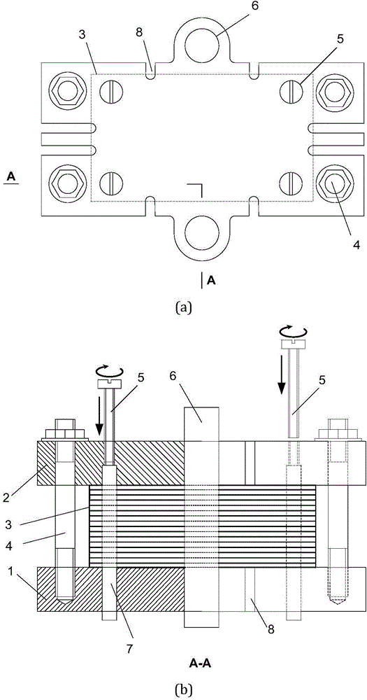
[0027] Such as figure 1 As shown in (a), this embodiment includes: a base 1, a top cover 2, a PCHE metal heat exchange plate 3, a stud 4, a pin-off screw 5, a guide rod 6, a positioning pin 7, and a welding groove 8, and laser welding is performed Before that, the positioning pin 7 and the guide rod 6 are put into the base first, and then the PCHE metal heat exchange plate is aligned with the positioning pin 7 and the guide rod 6 and stacked on the base. After all the PCHE metal heat exchange plates are installed, the top cover is aligned with the positioning pin 7 and the guide rod 6 and stacked on the PCHE metal heat exchange plate, and fastened with studs.

[0028] The base 1, the top cover 2 and the PCHE metal heat exchange plate 3 are aligned and fixed relative to each other through positioning pins and guide rods 6. The base 1 and the top cover 2 are connected by studs 4 to clamp the PCHE metal heat exchange plate 3 , and the guide rod 6 controls the direction of relati...


PUM


Abstract

The invention discloses a tool for laser welding of a printed circuit heat exchanger (PCHE). The tool for laser welding of the printed circuit heat exchanger comprises a base, a top cover, positioning pins, fastening studs and guide rods, wherein the base and the top cover are connected through the positioning pins, the fastening studs are arranged at the four corners of the base and the four corners of the top cover, and the guide rods are located on the two sides of the middle. The positioning pins vertically penetrate through multiple layers of the PCHE metal heat exchange plates which are located between the base and the top cover. The top cover and the base are connected in a fastened through the studs and tightly clamp the metal heat exchange plates located between the top cover and the base. The positioning pins are ejected out of the metal heat exchange plates through pin retreating screws, so that the shearing stress between the metal heat exchange plates is zero when the heat exchange plates of the tool are taken out, and thus the metal heat exchange plates are prevented from falling into pieces when the PCHE is taken out. According to the tool for laser welding of the PCHE, the technical requirements for strictly aligning the metal heat exchange plates of the PCHE, tightly clamping the metal heat exchange plates of the PCHE and conveniently taking a welded heat exchanger core out of the tool are met.

Description

technical field [0001] The invention relates to a device in the field of laser welding, in particular to a fixture for laser welding of a printed circuit board heat exchanger. Background technique [0002] Printed Circuit Heat Exchanger (PCHE) is a compact heat exchanger with excellent heat transfer performance and high efficiency. The different metal plates of the PCHE are first produced by electrochemical etching to produce grooves with a size of 1mm, and then initially fixed into blocks by laser welding, and finally laminated tightly through high temperature and high pressure diffusion bonding to form the entire heat exchanger core. If the metal plates of the PCHE are not fully aligned and there is a positional deviation greater than 0.1mm, this will cause the flow channel of the PCHE heat exchanger to be misaligned, affect the relative position of the fluid in the heat exchanger, and damage the inner core of the heat exchanger. Heat exchange between fluids. Since the w...

Claims


Application Information

Patent Timeline
IPC IPC(8): B23K26/70B23K37/04
CPCB23K37/0443B23K2101/14
Inventor 任滔王康硕吴国明丁国良
Owner SHANGHAI KELING ENERGY TECH
Learn More