Air conditioner device

A technology of air-conditioning equipment and humidifier, which is applied in the direction of air-conditioning system, lighting and heating equipment, high-efficiency regulation technology, etc., which can solve the problems of insufficient use demand and achieve the effect of increasing the flow rate

Inactive Publication Date: 2015-10-14
UNIMICRON TECH CORP
View PDF4 Cites 10 Cited by
  • Summary
  • Abstract
  • Description
  • Claims
  • Application Information

AI Technical Summary

Problems solved by technology

However, although the power consumption of the piezoelectric method is very low, it is not enough for the air-conditioning air supply that requires a large flow in the industry.

Method used


Image

  • Air conditioner device
  • Air conditioner device
  • Air conditioner device

Examples


Embodiment Construction

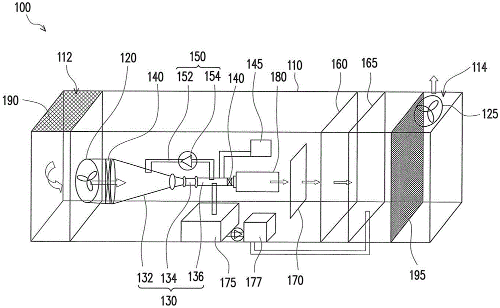
[0047] figure 1 is a schematic diagram of an air conditioner according to an embodiment of the present invention. see figure 1 The air conditioner 100 of this embodiment includes a chassis 110, an airflow introducing device 120, a supersonic nozzle 130, two valves 140, a vacuum pump 145, a communication device 150, a heater 160, a humidifier 165 and an airflow exporting device 125.

[0048] The chassis 110 includes an air inlet 112 and an air outlet 114 . In this embodiment, both the air inlet 112 and the air outlet 114 are located at figure 1 The upper side of the middle chassis 110 is close to the two sides, but the positions of the air inlet 112 and the air outlet 114 can be changed according to the site requirements. For example, the air inlet 112 and the air outlet 114 can also be respectively configured figure 1 The left and right sides of the middle chassis 110 are not limited thereto.

[0049] The airflow introduction device 120 is disposed in the chassis 110 near ...


PUM


Abstract

The invention discloses an air conditioner device. The air conditioner device comprises a case, an airflow guide-in device, a supersonic flow nozzle, two valve pieces, a vacuum pipe, a communication device, a heater, a humidifier and an airflow guide-out device. The case comprises an air inlet and an air outlet. The airflow guide-in device and the airflow guide-out device are arranged in the positions, close to the air inlet and the air outlet, in the case respectively. The supersonic flow nozzle comprises an air inlet part, a throat part and an exhaust part which are sequentially connected and are coaxial. The area of the section is gradually reduced from the end, far away from the throat part, of the air inlet part to the other end, close to the throat part, of the air inlet part, and the area of the section of the throat part is smaller than that of the exhaust part. The two valve pieces are arranged at the two ends of the supersonic flow nozzle respectively. The vacuum pump is communicated with the supersonic flow nozzle. The communication device is connected to the air inlet part and the exhaust part. The heater and the humidifier are arranged between the supersonic flow nozzle and the air outlet.

Description

technical field [0001] The invention relates to an air conditioner, and in particular to an air conditioner which saves energy and meets the demand of large flow. Background technique [0002] Air conditioning equipment is mainly used to control the temperature, humidity, air cleanliness and air circulation in the environment. Existing air-conditioning equipment is nothing more than utilizing the freezing method or the piezoelectric method to achieve the above-mentioned purpose. [0003] As far as the refrigeration method is concerned, it mainly uses the refrigerant to evaporate or condense under the action of the compressor, thereby causing the evaporation or condensation of the surrounding air to achieve the purpose of changing the temperature and humidity. However, the refrigeration method consumes a lot of electricity and requires the use of refrigerant circulation. In today's era of environmental protection and energy saving, repeated research on its energy-saving proc...

Claims


Application Information

Patent Timeline
Patent Type & Authority Applications(China)
IPC IPC(8): F24F5/00
CPCF24F5/00Y02B30/70
Inventor 廖本卫林豪杰
Owner UNIMICRON TECH CORP
Why Eureka
Try Eureka