
Power supply system and electronic device with the same

A technology of power supply system and reference voltage source, which is applied in the direction of control/regulation system, adjustment of electric variables, instruments, etc., can solve the problem of not being able to meet the special requirements of high-performance circuit systems, optimizing the frequency response characteristics of the voltage regulator chip, and not being able to supply power Adjustment and other issues to achieve the effect of improving anti-interference ability, flexible design, high power supply rejection ratio

Inactive Publication Date: 2015-10-14
36TH RES INST OF CETC
View PDF5 Cites 10 Cited by
  • Summary
  • Abstract
  • Description
  • Claims
  • Application Information

AI Technical Summary

Problems solved by technology

Generally, general-purpose voltage regulator chips often make compromises between these indicators, especially between the output voltage, load capacity, output voltage noise, and power supply rejection ratio. The design needs to be traded off, so it cannot meet high Special requirements for performance circuitry
However, some regulator chips with outstanding performance in one or several indicators cannot further optimize the frequency response characteristics of related indicators according to the actual electromagnetic environment and circuit environment, so as to make them more in line with actual needs.
Therefore, when the index conditions are relatively harsh, it is difficult to select qualified chips
Or, a problem with the power supply is discovered during debugging, but the power supply itself cannot be adjusted properly

Method used


Image

  • Power supply system and electronic device with the same
  • Power supply system and electronic device with the same
  • Power supply system and electronic device with the same

Examples


Embodiment Construction

[0033] In order to make the object, technical solution and advantages of the present invention clearer, the implementation manner of the present invention will be further described in detail below in conjunction with the accompanying drawings.

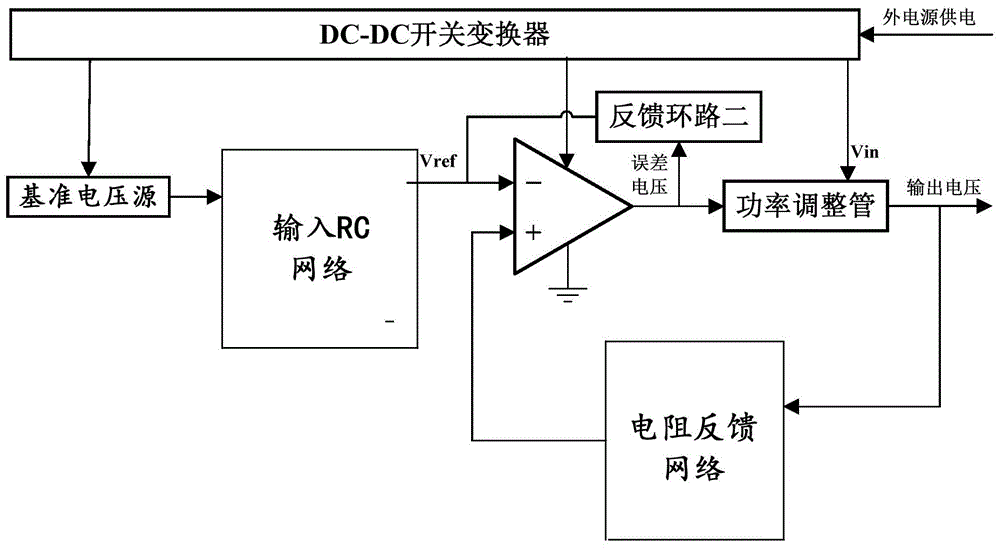
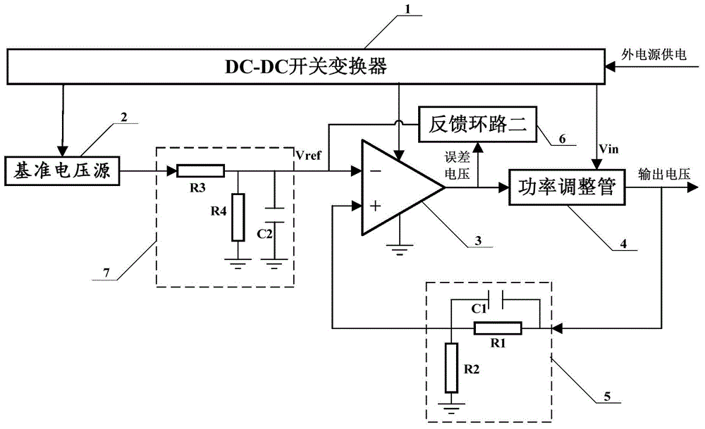
[0034] Such as figure 1 It is a schematic structural diagram of a power supply system provided by an embodiment of the present invention; the power supply system includes: a DC-DC switching converter, a reference voltage source, an operational amplifier, a power adjustment tube, a resistor feedback network, a feedback loop 2, an input RC network;

[0035] The DC-DC switching converter provides voltage for the operational amplifier and the power regulator tube, supplies power for the reference voltage source to obtain a reference voltage, and the reference voltage is used as the input voltage of the operational amplifier through the input RC network. Reference voltage; the resistance feedback network samples the output voltage, feeds b...


PUM


Abstract

The invention discloses a power supply system and an electronic device with the same. The power supply system provides voltage for an operational amplifier and a power adjustment pipe through a DC-DC switch converter and supplies power to a reference voltage source to obtain a reference voltage, and the reference voltage serves as a reference voltage of the operational amplifier by being input into an RC network. A resistance feedback network performs sampling on an output voltage and feeds collected signal results back to the operational amplifier, the operational amplifier amplifies the difference obtained by the comparison of the collected signal results and the reference voltage and then inputs the difference to the power adjustment pipe, and a second feedback loop serves as a zero pole of a negative feedback loop compensation loop of the operational amplifier. By use of a discrete device, the design is more flexible, the design of the power supply system which is high in power supply rejection ratio and low in noise is achieved, ripples and noises of an external power supply are restrained, the isolation degree of the external power supply in an electronic device is increased, and the antijamming capability of the system is improved.

Description

technical field [0001] The invention relates to the technical field of power electronics, in particular to a power supply system and electronic equipment with the power supply system. Background technique [0002] Power supply design is a key link in electronic system design. With the rapid development of radio technology, no matter in the field of communication technology or other related fields such as radio test and measurement, more and more stringent requirements are put forward for the power supply rejection ratio and noise of the power supply system. Any unwanted signals introduced into the system through external power lines, as well as the noise of the power system itself, may become a potential factor for radio system instability and interference. In order to meet the ever-increasing system requirements, the power supply in the radio system, as the conversion and isolation between the external power supply and the system power supply, must perform better in terms ...

Claims


Application Information

Patent Timeline
Patent Type & Authority Applications(China)
IPC IPC(8): G05F1/56
Inventor 钱焕裕周叶华程明
Owner 36TH RES INST OF CETC
Learn More