Contact thermal resistance modeling method considering elasticoplastic deformation of micro-bulge and thermal resistance of air medium

A technology of elastic-plastic deformation and contact thermal resistance, which is applied in special data processing applications, instruments, electrical digital data processing, etc., can solve the problems of not considering the thermal resistance of the gap air medium, not considering the elastic-plastic deformation of asperities, etc.

Active Publication Date: 2015-10-14
BEIJING UNIV OF TECH
View PDF3 Cites 15 Cited by
  • Summary
  • Abstract
  • Description
  • Claims
  • Application Information

AI Technical Summary

Problems solved by technology

At present, the modeling methods of thermal contact resistance mainly include the traditional Hertz contact model, the G-W model based on classical mechanics and statistics, the W-A contact model based on statistical parameters, and the M-B model based on the W-M function. The first three models have scale Dependence, affected by instrument resolution and sampling length, the latter model is comprehensive, deterministic, and scale-independent, but does not consider the elastic-plastic deformation of asperities, and does not consider the interstitial air medium thermal resistance

Method used


Image

  • Contact thermal resistance modeling method considering elasticoplastic deformation of micro-bulge and thermal resistance of air medium
  • Contact thermal resistance modeling method considering elasticoplastic deformation of micro-bulge and thermal resistance of air medium
  • Contact thermal resistance modeling method considering elasticoplastic deformation of micro-bulge and thermal resistance of air medium

Examples


Embodiment Construction

[0015] The present invention implements a contact thermal resistance modeling method considering the elastic-plastic deformation of the asperity and the thermal resistance of the air medium in the gap. The implementation of the present invention will be described in detail below in conjunction with the accompanying drawings.

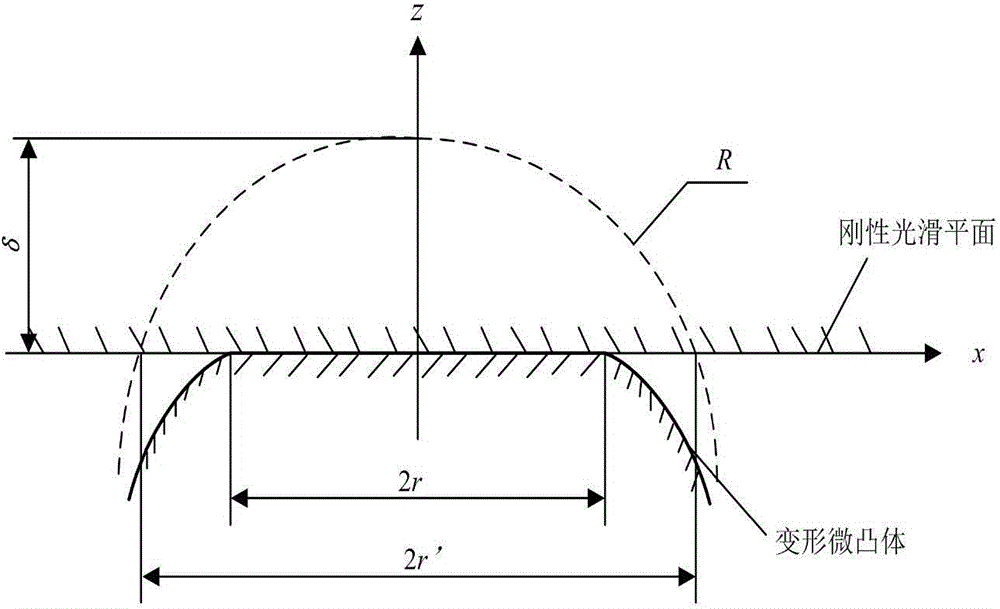
[0016] figure 1 is the contact schematic diagram of a single asperity, δ is the deformation amount of the top of the asperity, r' is the radius of the contact cross-sectional area of ​​the asperity, r is the contact radius of the asperity, and R is the curvature radius of the asperity top.

[0017] Step (1) Calculation of actual contact area and contact load of combined surface

[0018] 1.1 Elastic deformation

[0019] When a'>a' c1 When the asperity deforms elastically, the actual contact area of ​​a single asperity a ε , elastic contact load ΔF ε (a') and average contact pressure ΔP ε (a') can be expressed as

[0020] { ...


PUM


Abstract

The invention discloses a contact thermal resistance modeling method considering elasticoplastic deformation of a micro-bulge and thermal resistance of an air medium, wherein influence of the elasticoplastic deformation of the micro-bulge and the heat resistance of the air medium on the contact thermal resistance is considered. The method comprises: according to elastic deformation, elasticoplastic deformation and fully-plastic deformation of the micro-bulge, computing an actual contact area and contact load of a joint surface; then, respectively computing thermal constriction resistance and the heat resistance of the air medium, and computing total contact thermal resistance by virtue of combination of the thermal constriction resistance and the heat resistance of the air medium,; and finally, obtaining a relationship between the contact thermal resistance and the load by using a Matlab writing and computing program. The contact thermal resistance modeling method is characterized in that the influence of the elasticoplastic deformation of the micro-bulge and the heat resistance of the air medium is considered; the thermal constriction resistance, generated by elasticoplastic deformation, accounts for 15% of the total thermal constriction resistance; and when the load is relatively small, the influence of the heat resistance of the air medium is relatively large and cannot be ignored. The method provided by the invention can provide theoretical basis for computing the contact thermal resistance of boundary conditions for electro-spindle thermal state analysis.

Description

technical field [0001] The invention belongs to the field of research on the thermal characteristics of electric spindles, and relates to a contact thermal resistance modeling method considering the elastic-plastic deformation of asperities and the thermal resistance of the air medium. The method uses matlab to calculate and analyze the elastic-plastic deformation and the thermal resistance of the air medium. hindering effect. Background technique [0002] Motorized Spindle is one of the key components of CNC machine tools. Its characteristic is that the machine tool spindle and the spindle motor are combined into one, the machine tool spindle is directly driven by the built-in motor, and the main transmission chain of the machine tool is shortened to zero, thus realizing the zero transmission of the machine tool. The thermal characteristics of the electric spindle have a particularly significant impact on the machining accuracy of the machine tool. To establish a complete ...

Claims


Application Information

Patent Timeline
Patent Type & Authority Applications(China)
IPC IPC(8): G06F17/50
Inventor 赵永胜方翠蔡力钢马澄宇
Owner BEIJING UNIV OF TECH
Why Eureka
Try Eureka