APFC method of boost with no DC bias and no electrolytic capacitor

An electrolytic capacitor, no DC technology, applied in the field of APFC, can solve problems such as unfavorable high-power switching power supply modules being light and thin, reducing the reliability of switching power supplies, serious heating of energy storage inductors, etc. The effect of power factor

Inactive Publication Date: 2015-10-14
NANNING CHANGMENG ELECTRONICS TECH +2
View PDF3 Cites 1 Cited by
  • Summary
  • Abstract
  • Description
  • Claims
  • Application Information

AI Technical Summary

Problems solved by technology

Boost is the most common topology of APFC, and its energy storage inductor has DC bias, which will accelerate the aging of the magnetic core; the APFC energy storage inductor generates serious heat, which restricts the overall optimization of the APFC module in the direction of lightness, thinness, shortness, and smallness

Method used


Image

  • APFC method of boost with no DC bias and no electrolytic capacitor

Examples


Embodiment Construction

[0033] The specific embodiments of the present invention will be described in further detail below in conjunction with the accompanying drawings, but this does not constitute a limitation to the protection scope of the present invention.

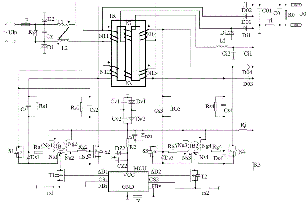
[0034] like figure 1 As shown, the APFC method of Boost without DC bias and without electrolytic capacitors is adopted as figure 1 The circuit structure shown is realized.

[0035] When the AC input power ~Uin has power, from the L terminal, through the fuse F to the safety capacitor Cx, the safety capacitor Cx is connected in parallel with the varistor Rv, and then returns to the other power supply terminal N, which is a conventional connection.

[0036] 1. Connect two sets of magnetically integrated high-frequency self-excited push-pull oscillation circuits into the Boost circuit. The specific method is:

[0037] Magnetic integrated transformer TR with "day"-shaped magnetic core, two sets of high-frequency inductance of high-frequency se...


PUM


Abstract

The invention discloses an APFC method of boost with no DC bias and no electrolytic capacitor. Two sets of high-frequency and self-excitation push-pull oscillation circuits are connected to a Boost circuit, so that the APFC process includes two low-frequency switch tubes controlled by a single-chip microcomputer MCU respectively regulate and control the high induction of the two sets of high-frequency and self-excitation push-pull oscillation circuits. The method improves the reliability when no electrolytic capacitor is used, and realizes control of accurate pulse duty ratio one by one. Real bottom switch QR is realized, heating is lowered, and output current with low ripples is realized. High power factor and power efficiency are realized, cost is low, and DC bias and electrolytic capacitor pollution problems can be prevented.

Description

technical field [0001] The invention belongs to the technical field of switching power supplies, and in particular relates to a Boost APFC method without DC bias and electrolytic capacitors. Background technique [0002] The traditional Boost topology is one of the basic methods of DC / DC conversion, especially suitable for boosting low-voltage DC to high-voltage DC output. Boost is the most common topology of APFC, and its energy storage inductor has DC bias, which will accelerate the aging of the magnetic core; the APFC energy storage inductor generates serious heat, which restricts the overall optimization of the APFC module in the direction of lightness, thinness, shortness, and smallness. However, it uses common bridge rectifiers and high-voltage electrolytic capacitors. Due to the large volume and short life of electrolytic capacitors, the reliability of switching power supplies is reduced, and it is not conducive to realizing light, thin, short and small high-power swi...

Claims


Application Information

Patent Timeline
IPC IPC(8): H02M1/42H02M7/217H02M3/337
CPCY02B70/10Y02P80/10
Inventor 石常青常小霞野娜王希天
Owner NANNING CHANGMENG ELECTRONICS TECH
Why Eureka
Try Eureka