Boost apfc circuit without DC bias and electrolytic capacitor

An electrolytic capacitor without direct current technology, which is applied in the direction of high-efficiency power electronic conversion, conversion of AC power input to DC power output, and conversion of DC power input to DC power output. Aging and other issues

Inactive Publication Date: 2017-09-22
深圳创智慧能电子科技有限公司
View PDF5 Cites 0 Cited by
  • Summary
  • Abstract
  • Description
  • Claims
  • Application Information

AI Technical Summary

Problems solved by technology

Boost is the most common topology of APFC, and its energy storage inductor has DC bias, which will accelerate the aging of the magnetic core; the APFC energy storage inductor generates serious heat, which restricts the overall optimization of the APFC module in the direction of lightness, thinness, shortness, and smallness
However, it uses common bridge rectifiers and high-voltage electrolytic capacitors. Due to the large volume and short life of electrolytic capacitors, the reliability of switching power supplies is reduced, and it is not conducive to the realization of light, thin, short and small high-power switching power supply modules.

Method used


Image

  • Boost apfc circuit without DC bias and electrolytic capacitor

Examples


Embodiment Construction

[0016] In the description of the present invention, it should be noted that unless otherwise specified and limited, the terms "installation", "connection" and "connection" should be understood in a broad sense, for example, it can be a fixed connection or a detachable connection , or integrally connected; may be mechanically connected, may also be electrically connected; may be directly connected, may also be indirectly connected through an intermediary, and may be internal communication between two components. Those of ordinary skill in the art can understand the specific meanings of the above terms in the present invention in specific situations.

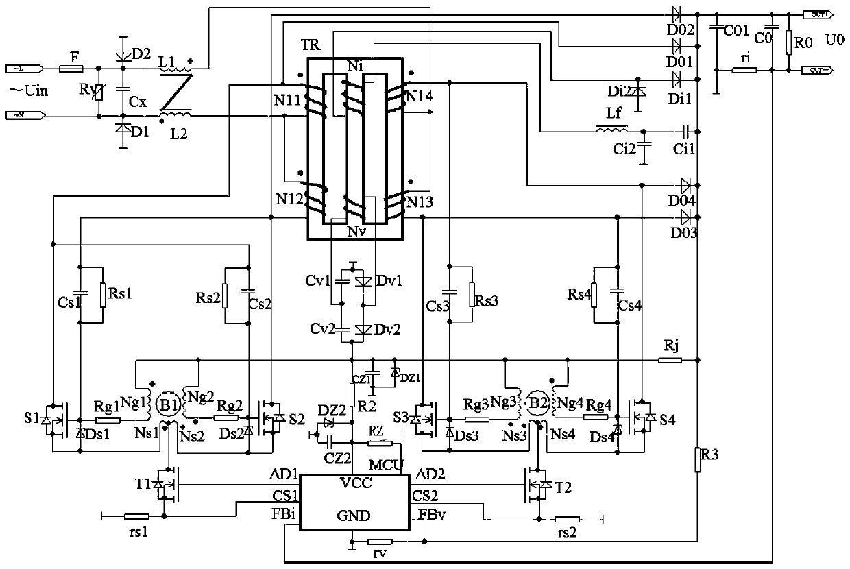
[0017] See figure 1 , figure 1 What is disclosed is a Boost APFC circuit without DC bias and without electrolytic capacitors, including the first set of high-frequency self-excited push-pull oscillation circuits, the second set of high-frequency self-excited push-pull oscillation circuits, MCU, and "日" font The magnetic integrat...


PUM


Abstract

The invention provides a Boost no-DC-magnetic-bias and no-electrolytic-capacitor APFC circuit which is characterized by comprising a first set of high-frequency self-excitation push-pull oscillation circuits, a second set of high-frequency self-excitation push-pull oscillation circuits, an MCU, a magnetic integrated transformer TR with a magnetic core shaped like a Chinese character "ri", and an MCU power supply sampling circuit. The winding N11 and the winding N12 of the first set of high-frequency self-excitation push-pull oscillation circuits are respectively wound on one edge column of the magnetic integrated transformer TR. The winding N14 and the winding N13 of the second set of high-frequency self-excitation push-pull oscillation circuits are respectively wound on the other edge column of the magnetic integrated transformer TR. The winding NV of the MCU power supply sampling circuit is wound on the center column of the magnetic integrated transformer TR. The MCU power supply sampling circuit provides electric energy and a sampling signal to the MCU according to an inductive electrical signal generated by the winding NV. The MCU processes the received sampling signal and controls a switching tube T1 and a switching tube T2 to work according to the processed information. The Boost no-DC-magnetic-bias and no-electrolytic-capacitor APFC circuit has advantages of reduction of heating, low ripple of output current, high power factor, high electric power efficiency and low cost.

Description

technical field [0001] The invention belongs to the technical field of switching power supplies, and in particular relates to a Boost APFC circuit without DC bias and electrolytic capacitors. Background technique [0002] The traditional Boost topology is one of the basic methods of DC / DC conversion, especially suitable for boosting low-voltage DC to high-voltage DC output. Boost is the most common topology of APFC, and its energy storage inductor has DC bias, which will accelerate the aging of the magnetic core; the APFC energy storage inductor generates serious heat, which restricts the overall optimization of the APFC module in the direction of lightness, thinness, shortness, and smallness. However, it uses common bridge rectifiers and high-voltage electrolytic capacitors. Due to the large volume and short life of electrolytic capacitors, the reliability of switching power supplies is reduced, and it is not conducive to realizing light, thin, short and small high-power sw...

Claims


Application Information

Patent Timeline
Patent Type & Authority Patents(China)
IPC IPC(8): H02M1/42H02M7/217H02M3/337
CPCY02B70/10Y02P80/10
Inventor 王桂风王桂光李智慧
Owner 深圳创智慧能电子科技有限公司
Why Eureka
Try Eureka