A frequency transmission system and method with post-compensation system

A technology of compensation system and transmission system, which is applied in the field of frequency transmission, can solve the problems of complex transmitter equipment, limited expandability, and only suitable transmission mode, so as to avoid complicated transmitter devices, improve transmission accuracy, and solve signal attenuation. problem effect

Active Publication Date: 2017-10-24
北京普测时空科技有限公司
View PDF5 Cites 0 Cited by
  • Summary
  • Abstract
  • Description
  • Claims
  • Application Information

AI Technical Summary

Problems solved by technology

This technology has a high transmission stability, but there is a big limitation for large-scale networking applications - its transmission mode is only suitable for point-to-point transmission, and each additional transmission path needs to add a set of transmission equipment
At the same time, since the main phase noise compensation function is completed by the transmitter, for the case where the frequency signal is transmitted from the frequency transmitter to multiple receivers, the phase transmitter compensation device will be concentrated on the transmitter, and will increase with the increase in the number of users, and then Causes problems such as complicated transmitter equipment and limited scalability

Method used


Image

  • A frequency transmission system and method with post-compensation system
  • A frequency transmission system and method with post-compensation system
  • A frequency transmission system and method with post-compensation system

Examples


Embodiment Construction

[0017] In order to make the object, technical solution and advantages of the present invention clearer, the present invention will be further described in detail below in combination with specific embodiments and with reference to the accompanying drawings.

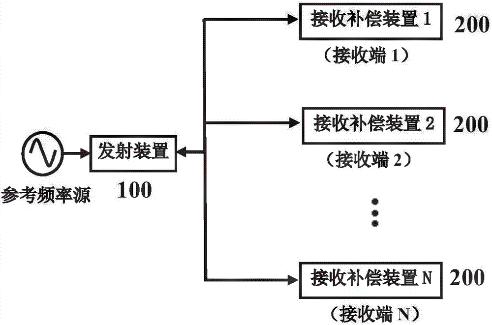
[0018] figure 1 It is a structural schematic diagram of the frequency signal transmission system behind the compensation device of the present invention.

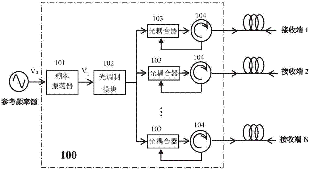
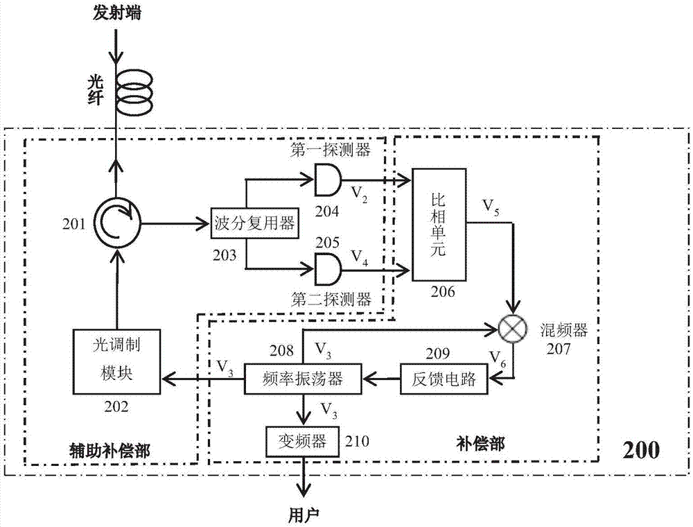
[0019] like figure 1 As shown, the frequency signal transmission system behind the compensation device of the present invention includes: a transmitting device 100, which is used to generate a frequency signal that is phase-locked to a reference frequency source, and modulate the frequency signal onto an optical signal to pass through one or more The optical fiber is transmitted to one or more receiving compensating devices 200 placed at the receiving end; the receiving compensating device having the same number as the receiving end is used to receive the optical sign...


PUM


Abstract

The invention discloses a compensation system rear-mounted frequency transmission system, comprising a transmitting device and one or a plurality of receiving compensation devices. The transmitting device is used for modulating a frequency signal with the phase locked at a reference frequency source to a light signal, and transmitting, through one or a plurality of optical fiber links, the frequency signal to one or a plurality of receiving compensation devices arranged at a receiving end. The receiving compensation device is used for receiving the frequency signal with optical fiber link phase noise from the transmitting device, taking the frequency signal as a first auxiliary compensation signal, loading a microwave signal generated by a frequency oscillator to the light signal to be transmitted by the optical fiber link and demodulated so as to obtain a second auxiliary compensation signal comprising the same phase noise as the first auxiliary compensation signal, generating a phase compensation signal on the basis of the first and second auxiliary compensation signals, performing feedback control on the phase of a signal output by the frequency oscillator, and reproducing a frequency signal with the phase locked at a frequency transmitting source. Through adoption of the system, the transmitting device can be simplified, and the problem of complication of co-transmitting terminal transmitting device probably caused by multilink parallel transmission of the frequency signal can be solved.

Description

technical field [0001] The invention relates to the technical field of frequency transmission, in particular to a frequency transmission system and method with a post-compensation system. Background technique [0002] The frequency transmission system is mainly used to release the frequency signal accurately and stably. The existing frequency transmission systems and transmission methods mainly use satellite or optical fiber as the transmission medium. Another authorized patent of the applicant of the present invention "Atomic Time Signal Transmission System and Transmission Method" (patent application number: CN201110186493.9) introduces a frequency signal transmission system and method that realizes ultra-long baseline (distance) through optical fiber. The system adopts the method of actively compensating the phase noise of the optical fiber link. Its main principle is to actively detect and pre-compensate the phase noise introduced by optical fiber transmission at the tr...

Claims


Application Information

Patent Timeline
Patent Type & Authority Patents(China)
IPC IPC(8): H04B10/25H04L7/033
Inventor 王力军王波高超白钰董婧雯朱玺
Owner 北京普测时空科技有限公司
Why Eureka
Try Eureka