
Linear polarization phase correction method for space universal rotating field azimuth errors

A technology of rotating magnetic field and azimuth error, which is applied in the directions of in vivo radio detectors, medical science, endoscopes, etc., can solve problems such as the inability to effectively eliminate the azimuth error of the coil mutual inductance magnetic field, destroy the matching relationship of resistance, and measure difficulties, etc., and achieve a solution Coil mutual inductance calculation and compensation are difficult, ensuring directionality and stability, and improving the effect of azimuth accuracy

Active Publication Date: 2015-10-21
DALIAN UNIV OF TECH
View PDF3 Cites 13 Cited by
  • Summary
  • Abstract
  • Description
  • Claims
  • Application Information

AI Technical Summary

Problems solved by technology

Practice has proved that this is not easy, because connecting the inductor satisfies the inductance matching relationship, but because the inductor itself has resistance, it destroys the resistance matching relationship
And because the calculation and measurement of the mutual inductance value between the coils is very difficult, it is impossible to effectively eliminate the magnetic field orientation error caused by the mutual inductance of the coils by separately compensating the three sets of coils

Method used

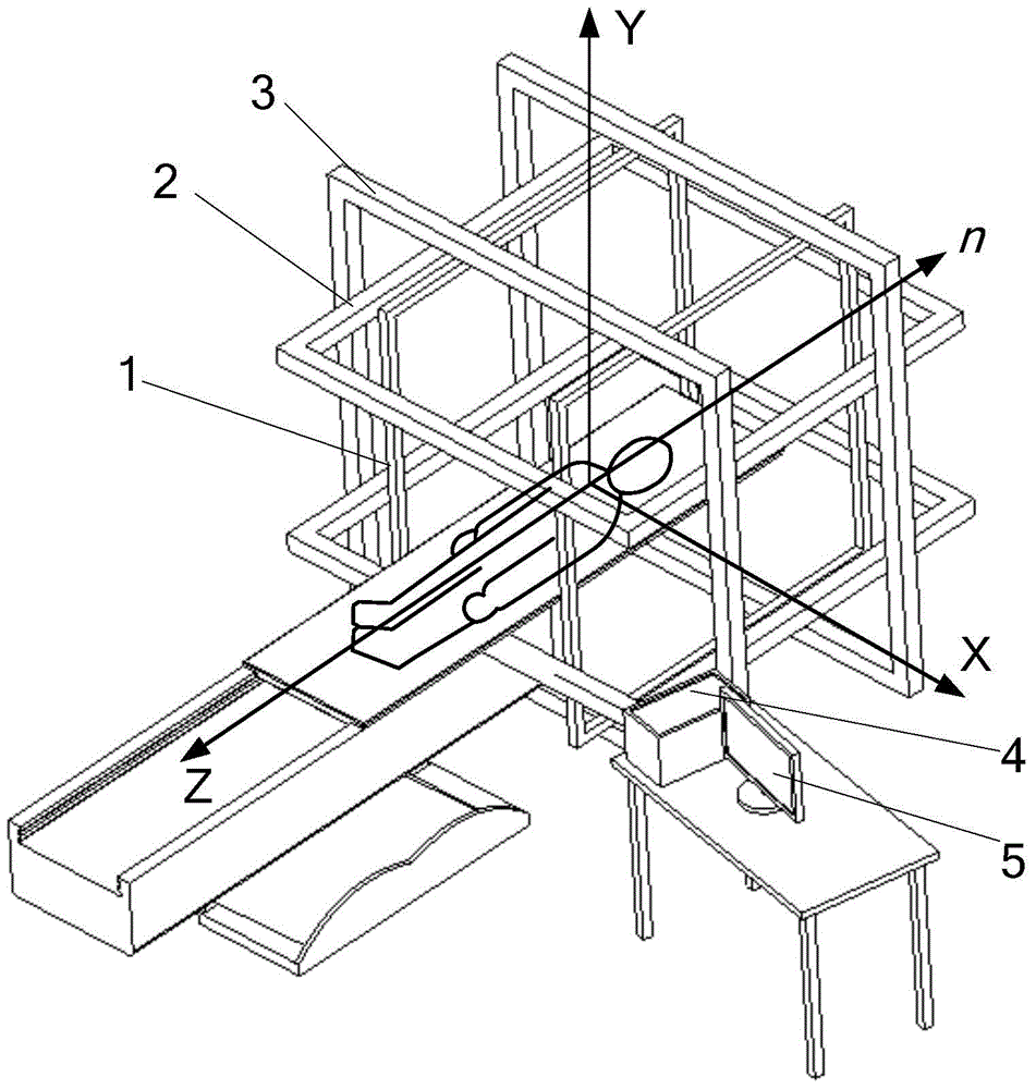
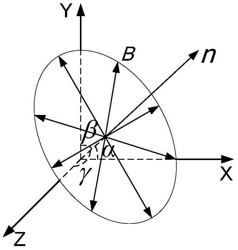

Image

  • Linear polarization phase correction method for space universal rotating field azimuth errors
  • Linear polarization phase correction method for space universal rotating field azimuth errors
  • Linear polarization phase correction method for space universal rotating field azimuth errors

Examples


Embodiment

[0100] Taking the correction of the azimuth error of the rotating magnetic field with the superposition frequency of 10Hz and the space direction angle of (45°, 60°, 60°) as an example, the theoretical estimation of the size of the azimuth error is carried out and the use of the linear polarization voltage phase difference compensation method to control The detailed process of digital compensation for system input voltage phase.

[0101] (1) Estimation of the azimuth error of the space universal rotating magnetic field

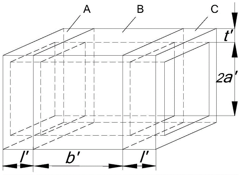
[0102] The structure of the square Helmholtz coil obtained by sequential quadratic programming is shown in the attached Figure 4 Its structural parameters are shown in Table 1.

[0103] Table 1 Optimized Helmholtz coil parameters

[0104]

[0105] According to the structural parameters of the Helmholtz coil, the theoretical values ​​of the resistance and inductance of the three sets of coils can be calculated. At the same time, the actual values ​​of th...


PUM


Abstract

The invention belongs to the technical field of automation engineering, relates to a phase correction method for space universal rotating field azimuth errors, and specifically discloses a linear polarization voltage phase difference compensation method. The method is characterized in that voltage phases of large coils serve as measuring references, the phase difference of the input voltage of small coils and the phase difference of the input voltage of intermediate coils are measured according to linear polarization characteristics of two-phase orthogonal harmonic signal superposition, digital compensation is performed on the input voltage, and the influence on the rotating field azimuth errors and caused by different electric parameters of the three sets of coils is eliminated. The beneficial effects of the method are that by employing the linear polarization voltage phase difference compensation method, the superposition rotating field azimuth errors due to the difference of the electric parameters of the three sets of Helmholtz coils with different structures can be eliminated, the azimuth accuracy of the space universal rotating field can be improved, the influence on the azimuth accuracy of the space universal rotating field and caused by coil mutual inductance can especially be eliminated, and a technical problem that coil mutual inductance calculation and compensation are difficult can be solved.

Description

technical field [0001] The invention belongs to the technical field of automation engineering, and relates to a method for correcting the azimuth error of a space universal rotating magnetic field superimposed by a three-axis orthogonal Helmholtz coil. The linear polarization characteristics of the superposition of harmonic signals, respectively measure the phase difference of the input voltage of the small coil and the middle coil, and digitally compensate the input voltage, so that the magnetic induction intensity generated by the three sets of orthogonal Helmholtz coils strictly meets the superposition ideal The phase requirements of the rotating magnetic field eliminate the inconsistency of the electrical parameters (resistance, inductance) of the three sets of Helmholtz coils and the influence of the mutual inductance between the coils on the azimuth accuracy of the universal rotating magnetic field in space. Background technique [0002] With the continuous advancement...

Claims


Application Information

Patent Timeline
Patent Type & Authority Applications(China)
IPC IPC(8): A61B1/00A61B5/07
CPCA61B1/00158A61B1/041A61B5/073
Inventor 张永顺苏忠侃迟明路白建卫杨振强
Owner DALIAN UNIV OF TECH
Learn More