Eureka AIR delivers breakthrough ideas for toughest innovation challenges, trusted by R&D personnel around the world.

Power-driven pneumatic extinguisher

A wind fire extinguisher, electric technology, applied in fire rescue, etc., can solve the problems of complex structure, noise and exhaust gas pollution, long time, etc., and achieve the effect of good controllability, strong adaptability and simple structure

Active Publication Date: 2015-10-21
BAOTOU BEIGONG MACHINERY
View PDF5 Cites 2 Cited by
  • Summary
  • Abstract
  • Description
  • Claims
  • Application Information

AI Technical Summary

Problems solved by technology

[0003] Since the traditional wind fire extinguisher uses a fuel engine as the power component, the related fuel, fuel tank, carburetor, spark plug, manual oil pump, etc. must be equipped, which makes the traditional wind fire extinguisher not only complicated in structure and difficult to maintain, but also difficult to start ( It will even be difficult to start at low temperature), and it is not easy to operate, so it takes too long before it is put into work, or even cannot be put into use normally, which is very likely to delay the timing of fire extinguishing and cause greater losses; in addition, because the fuel engine is used as a power component, in At the scene of a fire, the traditional wind fire extinguisher may spontaneously ignite and cause personal injury; in addition, when the fuel engine works as a power component, it is not only inefficient, but also produces strong vibration, noise and exhaust gas pollution. Traditional fire extinguishing device fire extinguishing costs increase

Method used


Image

  • Power-driven pneumatic extinguisher
  • Power-driven pneumatic extinguisher

Examples


Embodiment Construction

[0018] In order to facilitate a further understanding of the structure and effects of the present invention, the detailed description is as follows in conjunction with the accompanying drawings and preferred embodiments.

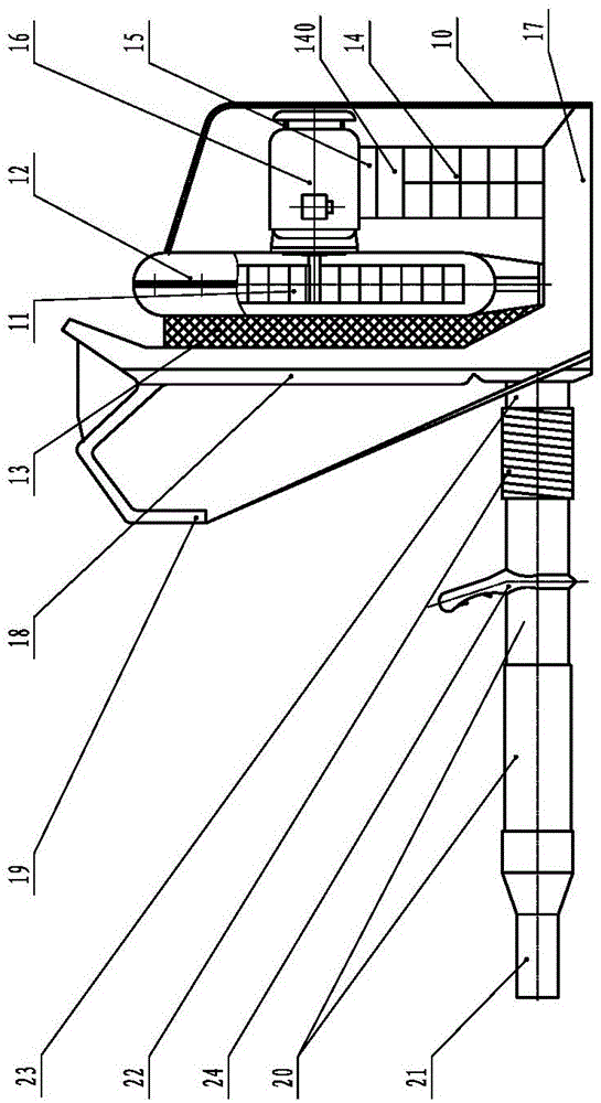
[0019] Such as figure 1 As shown, an electric wind fire extinguisher of the present invention includes a body that can generate high-speed airflow and an exhaust duct connected to the body. A centrifugal fan 11 that drives and generates high-speed airflow.

[0020] Such as figure 1 As shown, the exhaust duct in the present invention includes a straight air duct 20, a curved air duct 23 and a nozzle 21. One end of the straight air duct 20 is connected to the curved air duct 23, and the other end is connected to the nozzle 21. The curved air duct 23 is connected to the machine body. Connected, the high-speed airflow produced by the body is sprayed out by the nozzle 21 through the curved air pipe 23 and the straight air pipe 20, and the fire scene is extingui...


PUM


Abstract

The invention discloses a power-driven pneumatic extinguisher, comprising a machine body capable of generating high speed airflow and an exhaust pipeline connected with the machine body, wherein the machine body comprises a shell, an electric drive system arranged in the shell, and a centrifugal fan which is driven by the electric drive system and generates the high speed airflow. The power-driven pneumatic extinguisher has the advantages of being good in controllability, simple in structure, energy-saving, environment-friendly, high in efficiency, safe, reliable and the like, and can be used for fire extinction and debris cleaning.

Description

technical field [0001] The invention relates to a wind fire extinguishing device, in particular to a rechargeable electric wind fire extinguisher in the field of new energy technology. Background technique [0002] At present, the existing wind-powered fire extinguishing devices usually use a fuel engine to drive a centrifugal fan fixedly connected to its output shaft to rotate at high speed. Creates a powerful high-speed air jet for extinguishing fires and clearing debris. [0003] Since the traditional wind fire extinguisher uses a fuel engine as the power component, the related fuel, fuel tank, carburetor, spark plug, manual oil pump, etc. must be equipped, which makes the traditional wind fire extinguisher not only complicated in structure and difficult to maintain, but also difficult to start ( It will even be difficult to start at low temperature), and it is not easy to operate, so it takes too long before it is put into work, or even cannot be put into use normally,...

Claims


Application Information

Patent Timeline
Patent Type & Authority Applications(China)
IPC IPC(8): A62C15/00A62C31/00A62C37/00
CPCA62C15/00A62C31/00A62C37/00
Inventor 芦晓民刘清玉李雄飞
Owner BAOTOU BEIGONG MACHINERY
Why Eureka
Eureka Blog
Learn More