All-position pipeline welding workstation

A welding workstation, all-position technology, applied in the direction of welding equipment, welding equipment, auxiliary welding equipment, etc., to achieve the effect of small rotational inertia, accurate positioning, and improve work accuracy and work efficiency

Active Publication Date: 2015-10-21
扬州鑫凯诚机器人系统有限公司
View PDF9 Cites 6 Cited by
  • Summary
  • Abstract
  • Description
  • Claims
  • Application Information

AI Technical Summary

Problems solved by technology

[0003] The present invention aims at the technical problems existing in the prior art, and provides an all-position pipe welding workstation. This technical solution can effectively solve the related problems existing in the existing automatic pipe welding equipment. The welding chuck device on the upper part is used together to realize the transportation of pipe fittings and the purpose of convenient welding of prefabricated pipes. It has the characteristics of flexible and convenient disassembly, safety and reliability, and is easy to operate. It improves the welding quality and welding efficiency and reduces the labor of the operator. Strength and production costs and safety incident rates

Method used


Image

  • All-position pipeline welding workstation
  • All-position pipeline welding workstation
  • All-position pipeline welding workstation

Examples


Embodiment 1

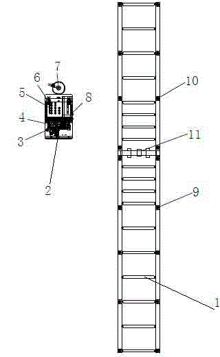
[0026] see figure 1 , an all-position pipeline welding workstation, the welding workstation includes a pipe cutting bevel device 1 and an open welding device 2, and the open welding device includes a welding chuck 4, an argon arc welding machine 5, a wire feeder 6, and a water tank 3 , argon cylinder 7, control electrical box 8, the pipe cutting and beveling device includes a front end 9 of a conveying line, a rear end 10 of a conveying line and a pipe cutting and beveling machine 11 arranged between the front end of the conveying line and the rear end of the conveying line. The technical scheme has a reasonable and compact structure and is easy to use. The joint use of the clamping welding device and the pipe cutting and breaking device can realize the purpose of cutting the pipe fittings, beveling and welding between the pipe fittings. It has the characteristics of flexible, convenient, safe and reliable disassembly. , It facilitates the operation, improves the welding quali...

Embodiment 2

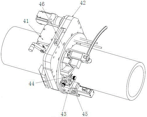
[0028] see figure 1 , figure 2 , as an improvement of the present invention, the welding chuck includes a pipe clamping mechanism 41, an open rotation mechanism 42, a welding torch swing mechanism 43, a manual slide mechanism 44 in the X direction, a manual slide mechanism 45 in the Y direction, and an automatic retreat mechanism. The needle mechanism 46, the pipe clamping mechanism 41 is fixed on the bottom of the open rotating mechanism 42 by bolts, the welding torch swing mechanism 43 is connected with the C-shaped rotating disk on the open rotating mechanism 42 using bolts, and the Y Direction manual slide mechanism 45 is connected with the trapezoidal nut slider on the welding torch swing mechanism 43, the X direction manual slide mechanism 44 is connected with the Y direction manual slide mechanism 45, and the automatic needle withdrawal mechanism 46 is connected with the X direction Manual slide mechanism 44 is connected. The welding chuck described in the technical ...

Embodiment 3

[0030] see figure 1 , figure 2 , as an improvement of the present invention, the welding chuck 4, argon arc welding machine 5, wire feeder 6, water tank 3, argon gas bottle 7, and control electric box 8 are installed on a movable trolley, and the welding chuck The head is set on one side of the mobile trolley, and the welding chuck is installed on the pipe to perform welding. Four casters are installed at the bottom of the mobile trolley, and two directional wheels and two universal wheels are set to facilitate movement and positioning. The rest of the structures and advantages are exactly the same as in Embodiment 1.


PUM


Abstract

The invention relates to an all-position pipeline welding workstation. The all-position pipeline welding workstation is characterized by comprising a pipeline cutting and beveling device and an open type welding device. The open type welding device comprises a welding chuck, an argon arc welding machine, a wire feeder, a water tank, an argon gas bomb and a control electric box. The pipeline cutting and beveling device comprises a conveying line front end, a conveying line rear end and a pipeline cutting and beveling machine arranged between the conveying line front end and the conveying line rear end. Through coordinate usage of the pipeline cutting and beveling device and the welding chuck device on a movable trolley, the purposes of conveying of pipelines and convenient welding of prefabricated pipelines are achieved; the characteristics of flexible and convenient disassembly, safety, reliability and the like are achieved; operation is convenient; the welding quality and efficiency are improved; labor intensity of operators is relieved; production cost and the occurrence rate of safety accidents are reduced.

Description

technical field [0001] The invention relates to a welding workstation, in particular to an all-position pipeline welding workstation, which belongs to the technical field of welding equipment. Background technique [0002] At present, for the welding of medium-sized and long pipelines, manual welding is mainly used, and multi-layer operations are inefficient, and the quality is not stable enough. The welding arc, molten steel, and solution are likely to cause direct damage to workers. The operating cost is very high. Therefore, in In terms of welding equipment, enterprises urgently need to introduce automatic welding equipment. Automatic welding equipment will gradually replace manual labor as the main equipment. At present, the open welding equipment used in the market mainly uses the principle of leverage to clamp pipes, resulting in a small range of clamping pipe diameters. Its structure The wire feeder is integrated on the welding chuck. The wire feeding disc is not a c...

Claims


Application Information

Patent Timeline
Patent Type & Authority Applications(China)
IPC IPC(8): B23K9/167B23K9/022B23K9/028B23K37/053B23K9/28B23K37/00B23K101/06
CPCB23K9/022B23K9/0282B23K9/167B23K9/287B23K37/003B23K37/053B23K2101/06
Inventor 赵凯张辉谭刚
Owner 扬州鑫凯诚机器人系统有限公司
Why Eureka
Try Eureka