
Blanking manipulator

A manipulator and cutting technology, applied in the field of machinery, can solve the problems of high risk, high labor intensity of workers, and high enterprise cost, and achieve the effects of convenient maintenance and disassembly, reducing work intensity and enterprise cost, and improving positioning accuracy.

Active Publication Date: 2015-10-21
WECAN M&E SHANGHAI
View PDF5 Cites 12 Cited by
  • Summary
  • Abstract
  • Description
  • Claims
  • Application Information

AI Technical Summary

Problems solved by technology

The labor intensity of workers is high, the risk is high, and the cost of enterprises is high

Method used


Image

  • Blanking manipulator
  • Blanking manipulator
  • Blanking manipulator

Examples


Embodiment Construction

[0033] In order to have a further understanding and understanding of the structural features of the present invention and the achieved effects, the preferred embodiments and accompanying drawings are used for a detailed description, as follows:

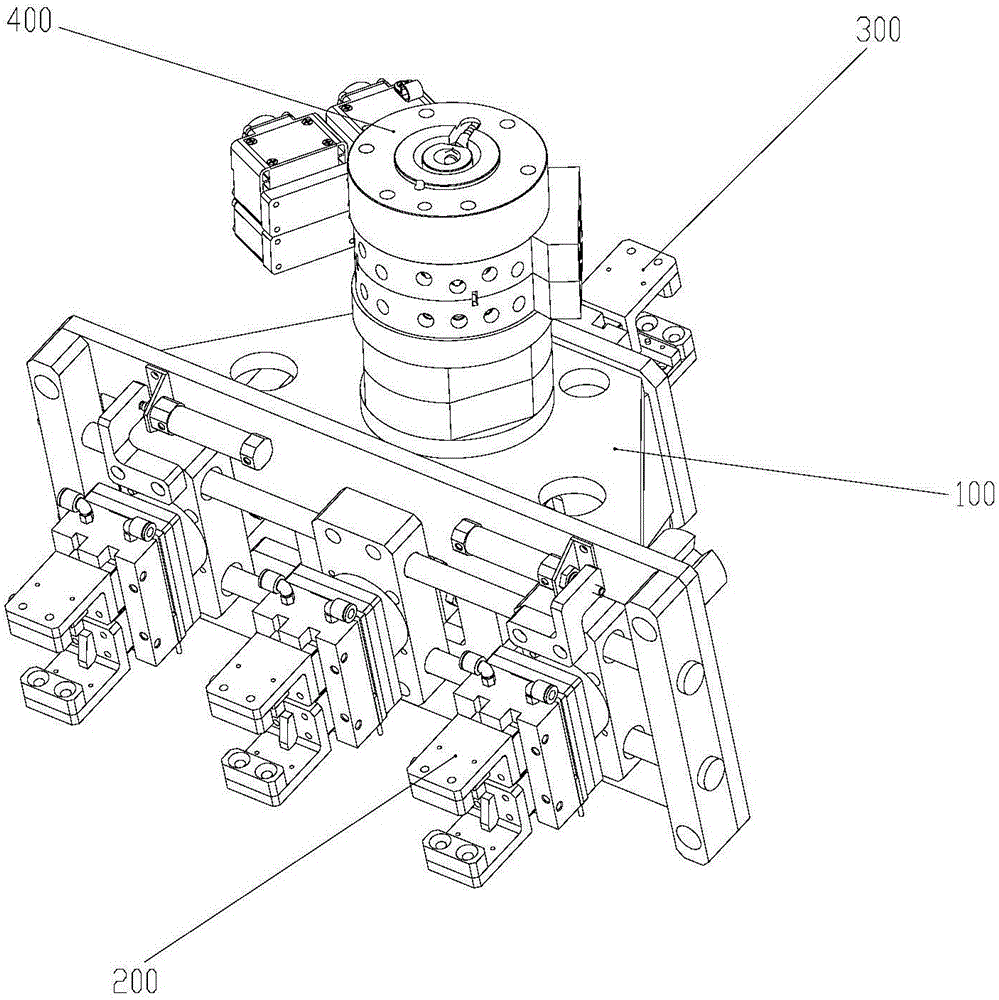
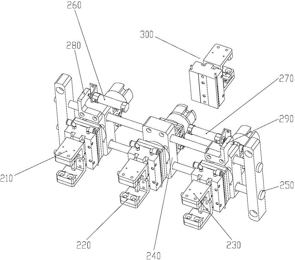
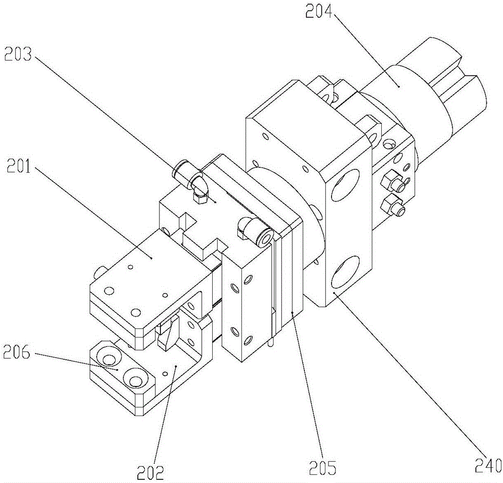
[0034] see figure 1 As shown, a blanking manipulator includes a frame 100, a three-handle assembly 200, a single-handle assembly 300, a gun changing tray 400 and a pneumatic control assembly (not shown in the figure), and the three-handle assembly 300 is set At the bottom of the frame 100, the single gripper assembly 300 is arranged on the top of the frame 100, the gun change tray 400 is arranged on the side of the frame 100, the pneumatic control assembly is arranged inside the frame 100, and the pneumatic control assembly controls the three gripper assembly 200 and the single gripper Hand assembly 100 movements. The setting of the gun change tray 100 allows the robot to quickly replace the mechanical gripper under different require...


PUM


Abstract

The invention relates to a blanking manipulator comprising a frame, a three-claw assembly, a single-claw assembly, a gun changing plate, and a pneumatic control assembly. The three-claw assembly is arranged at the bottom of the frame; the single-claw assembly is arranged at the top of the frame; the gun changing plate is arranged at the side; and the pneumatic control assembly is arranged inside the frame. The pneumatic control assembly controls the three-claw assembly and the single-claw assembly to move. The blanking manipulator has the following beneficial effects: with the blanking manipulator, the workpiece positioning and clamping, workpiece capturing and releasing, and workpiece rotation can be realized; the workpiece positioning precision is improved; a requirement of different intervals is met; the mechanical claw can be replaced rapidly; on the basis of the integrated mode, the maintenance and dismounting become convenient; the manual blanking is replaced; the work strength of the worker and the enterprise cost are reduced; and automation of the production can be realized in a real sense.

Description

technical field [0001] The invention relates to the technical field of machinery, in particular to a material-cutting manipulator. Background technique [0002] At present, in the field of mechanical processing, the production and processing of products requires multiple processes. In the process of entering the next process from one process to the next process, various transmission devices are required for transportation. How to quickly and accurately transport materials to the work station is the key The key to improving ergonomics and processing quality as well as production safety. So far, some enterprises still use manual operation to grab, carry and release the cylinder body. The labor intensity of workers is high, the danger is great, and the cost of enterprises is high. Contents of the invention [0003] The object of the present invention is to solve the above problems, and to provide a cutting machine for grabbing, carrying and releasing the cylinders located a...

Claims


Application Information

Patent Timeline
Patent Type & Authority Applications(China)
IPC IPC(8): B23Q7/04B23Q41/02
CPCB23Q7/048B23Q41/02
Inventor 杨凯李坤叶
Owner WECAN M&E SHANGHAI
Learn More