Automatic sand flushing device for upper electric field water discs

An automatic flushing and water tray technology, applied in the direction of electric/magnetic dehydration/demulsification, electric/magnetic refining, etc., can solve the problems of occupying space, affecting the normal operation of the upper electric field, etc., to reduce deposition and excellent self-lubricating performance. Effect

Inactive Publication Date: 2015-10-21
JIANGSU GOLDEN GATE ENERGY & EQUIP CO LTD +1
View PDF2 Cites 2 Cited by
  • Summary
  • Abstract
  • Description
  • Claims
  • Application Information

AI Technical Summary

Problems solved by technology

Due to the fact that the current equipment in the petrochemical industry is inspected after three years of operation, after three years of operation, the stubborn sediment and mechanical impurities accumulated o

Method used


Image

  • Automatic sand flushing device for upper electric field water discs
  • Automatic sand flushing device for upper electric field water discs
  • Automatic sand flushing device for upper electric field water discs

Examples


Embodiment Construction

[0018] The present invention will be further described below in conjunction with the accompanying drawings and embodiments.

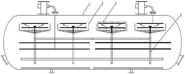
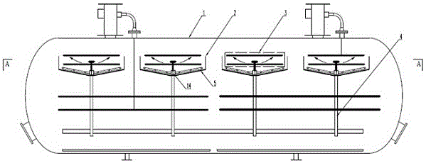
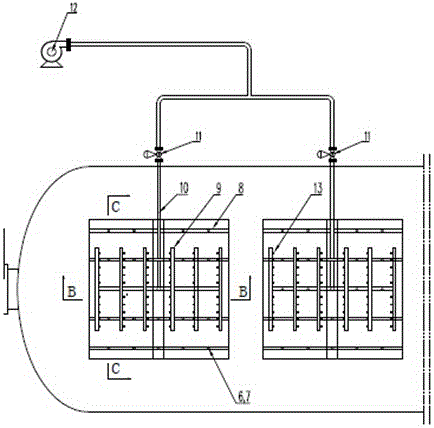
[0019] Such as figure 2 As shown, on the bottom surface of each water tray 2, one deck of automatic desanding plate 5 is compounded. The material of automatic desanding plate 5 is polytetrafluoroethylene sheet, or is sprayed polytetrafluoroethylene. The thickness of the PTFE sheet or sprayed PTFE coating is determined according to the degree of wear on the surface of the automatic sand removal plate by the deposited sediment and mechanical impurities, and the design service life. After the surface of the PTFE sheet is treated, it can be pasted on the bottom surface of the electric desalination tank. Also can weld several screws 6 at the bottom of every water tray 2, with nut 7 and pressing plate 8, the polytetrafluoroethylene sheet is pressed on the bottom of every water tray 2 (referring to figure 2 , Figure 5 ). Above the bottom of every water...


PUM


Abstract

The invention relates to an automatic sand flushing device for upper electric field water discs. The automatic sand flushing device for the upper electric field water discs comprises automatic sand removing plates, a back flushing inlet pipe, multiple back flushing water pipes, multiple spray nozzles and downpipes, the automatic sand removing plates are arranged on the upper sides of the bottom faces of the corresponding water discs, the water discs are each in a V shape, and correspondingly, a water groove is formed in the bottom of each water disc; the back flushing water pipes are arranged above the automatic sand removing plates, the spray nozzles are evenly distributed on the back flushing water pipes, the back flushing inlet pipe is communicated with the back flushing water pipes to supply water to the back flushing water pipes, and the downpipes are communicated with the water grooves in the bottoms of the water discs. By means of the automatic sand flushing device for the upper electric field water discs, the defect that sediments and mechanical impurities cannot be removed automatically through original double-oil-taking and double-electric-field electric desalting and dewatering equipment in the crude oil desalting and dewatering process of upper electric fields is overcome.

Description

technical field [0001] The invention relates to the field of electric desalination tanks, in particular to an automatic sand flushing device for an upper electric field water tray. Background technique [0002] Double oil inlet double electric field electric desalination and dehydration technology In the space above the center line of the electric desalination tank 1, several square or rectangular semi-closed water pans 2 are arranged, and each water pan 2 is equipped with an upper electric field unit 3 ( see figure 1 ). Since the crude oil contains more sediment and mechanical impurities, it will settle to the bottom of each water pan 2 during the desalination and dehydration process of crude oil. Although the bottom of the water pan 2 has been designed as a sloping plate, some sediment and mechanical impurities It can be taken away with the discharge of salty sewage, but there is still a part of stubborn silt and mechanical impurities deposited on the sloping plate at th...

Claims


Application Information

Patent Timeline
IPC IPC(8): C10G33/02C10G32/02
Inventor 蒋长胜
Owner JIANGSU GOLDEN GATE ENERGY & EQUIP CO LTD
Why Eureka
Try Eureka