
A staged toilet flushing method

A staged, toilet technology, applied in the field of sanitary ware, can solve the problems of unstable cleaning effect of toilet pool dirt receiving surface, spray flushing effect, inconsistent water volume, shortened siphon time, etc., to achieve stable spray effect and maintenance Continue and promote the effect of siphon generation

Active Publication Date: 2016-11-30
XIAMEN R&T PLUMBING TECH
View PDF5 Cites 0 Cited by
  • Summary
  • Abstract
  • Description
  • Claims
  • Application Information

AI Technical Summary

Problems solved by technology

[0004] The water source supply device supplies water to the scrubbing circle and the spray hole at the same time. On the one hand, the water quantity distributed to the scrubbing circle water and the spray hole cannot achieve the best effect. Consistency, always more and sometimes less, resulting in unstable cleaning effect on the dirt receiving surface of the toilet pool or jet flushing effect; It flows to the water seal at the bottom of the toilet pool after the material receiving surface. At the same time, water is supplied to the scrubbing ring and the spray hole, which will cause the flushing water to form a siphon when the flushing water has not yet flowed to the bottom of the toilet pool. It does not make full use of the washing water to participate in the siphon, which is not conducive to promoting the generation of the siphon, and leads to a higher injection pressure and a smaller injection flow required for the jet siphon, and after the higher pressure injection generates the siphon, the siphon is due to the higher pressure and the toilet. Insufficient pool water will lead to excessive siphon force and shortened siphon time, which will eventually lead to poor siphon effect and waste of water resources

Method used

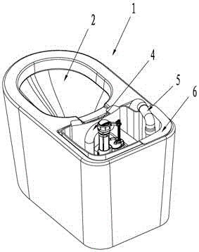
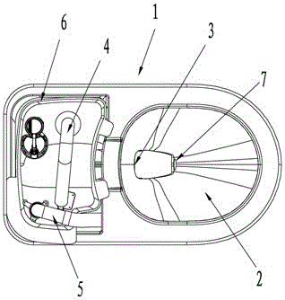
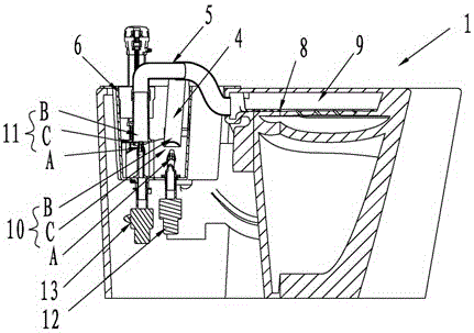

Image

  • A staged toilet flushing method
  • A staged toilet flushing method
  • A staged toilet flushing method

Examples


Embodiment 1

[0025] Embodiment 1: (the toilet flushing device includes a water tank and two pump devices, and the water supply source of the flushing water pipeline and the flushing water pipeline includes the water in the water tank)

[0026] Such as Figure 1-3 As shown, in order to solve the technical problems in the background technology, the present invention provides a staged toilet flushing method, which controls the flushing water and flushing water respectively, including the following steps: S1, turning on the flushing water , wash the dirt receiving surface of the toilet pool, turn off the washing water after the predetermined time period T1 is turned on for the washing water; S2, turn on the flushing water, flush the spray hole at the bottom of the toilet pool to make the toilet waste discharge pipe form a siphon; S3. After the flushing water is turned on for a predetermined time period T2, the flushing water is turned on again. The flushing water first washes the dirt receivin...

Embodiment 2

[0037] Embodiment 2: (the toilet flushing device does not include a water tank, but includes a control valve, and the water supply source of the two pipelines of washing water and flushing water is the water in the water supply pipe network)

[0038] In order to solve the technical problems in the background technology, the present invention provides a step-by-step toilet flushing method, which controls the flushing water and flushing water respectively, including the following steps: S1, turning on the flushing water, flushing the toilet Wash the dirt receiving surface of the pool, and turn off the washing water after opening the predetermined time period T1 of the washing water; S2, turn on the flushing water, and flush the spray holes at the bottom of the toilet pool to form a siphon for the toilet waste discharge pipe; S3, in the After the flushing water is turned on for a predetermined time period T2, the flushing water is turned on again. The flushing water first washes t...

Embodiment 3

[0043] Embodiment 3: (the toilet flushing device does not include a water tank, but includes two control valves, and the water supply source of the two pipelines of flushing water and flushing water is the water in the water supply pipe network)

[0044] In order to solve the technical problems in the background technology, the present invention provides a step-by-step toilet flushing method, which controls the flushing water and flushing water respectively, including the following steps: S1, turning on the flushing water, flushing the toilet Wash the dirt receiving surface of the pool, and turn off the washing water after opening the predetermined time period T1 of the washing water; S2, turn on the flushing water, and flush the spray holes at the bottom of the toilet pool to form a siphon for the toilet waste discharge pipe; S3, in the After the flushing water is turned on for a predetermined time period T2, the flushing water is turned on again. The flushing water first wash...


PUM


Abstract

The invention discloses a method for flushing a toilet by stages. By employing the method, the discharge of cleaning water and flushing water and be respectively controlled. The method comprises following methods: S1, turning on the cleaning water to wash the sewage bearing surface of a toilet pool, and turning off the cleaning water after the cleaning water is turned on for a preset period T1; S2, turning on the flushing water to flush jet holes at the bottom the toilet pool, so that the sewage in the toilet can be discharged from a pipe, and a siphon phenomenon is formed; S3, turning on the cleaning water again after the flushing water is turned on for a preset period T2, wherein the cleaning water washes the sewage bearing surface of the toilet pool firstly, and then the cleaning water and the flushing water are discharged from the toilet pool the siphon effect; and S4, simultaneously turning off the cleaning water and the flushing water after the cleaning water is turned on for a preset period T3 for the second time. The flushing method is carried out by stages, the toilet has a good siphon effect, the flushing performance for the toilet can be improved, water can be saved at a certain degree, the method is easy and feasible, and obvious effects can be achieved.

Description

technical field [0001] The invention relates to the field of sanitary ware, in particular to a staged toilet flushing method. Background technique [0002] The jet siphon toilet adopts the siphon principle in fluid mechanics. After the flushing device is started, the toilet pipeline is in a vacuum state, and the sewage pipeline generates a strong negative pressure instantly. Due to the effect of atmospheric pressure, a liquid column height difference is formed, resulting in a pressure difference. Make the water flow from the high water level with high pressure to the low water level with low pressure, and fill the sewage pipes to generate a siphon phenomenon, thereby sucking away the sewage until all the water flows out of the toilet pool. The jet siphon toilet has strong flushing power, quietness, and odor isolation effects. Now the general toilets on the market have adopted the jet siphon structure. [0003] Most of the existing jet-type toilets include a scrubbing ring a...

Claims


Application Information

Patent Timeline
Patent Type & Authority Patents(China)
IPC IPC(8): E03D1/28E03D1/38E03D5/01
Inventor 钟志军陈海滨
Owner XIAMEN R&T PLUMBING TECH
Learn More