
High-flow-rate underground oil-water separation and annular space testing and regulating system

A technology of oil-water separation and oil-water separator, which is applied in the direction of wellbore/well components, production fluid, earthwork drilling and production, etc. It can solve the problems of accurate monitoring and control of the flow rate of large-capacity downhole oil-water separation system, and achieves a wide range of applications. , The structure of the system is simple and the working conditions are stable

Active Publication Date: 2015-10-21
CHINA NAT OFFSHORE OIL CORP +1
View PDF3 Cites 25 Cited by
  • Summary
  • Abstract
  • Description
  • Claims
  • Application Information

AI Technical Summary

Problems solved by technology

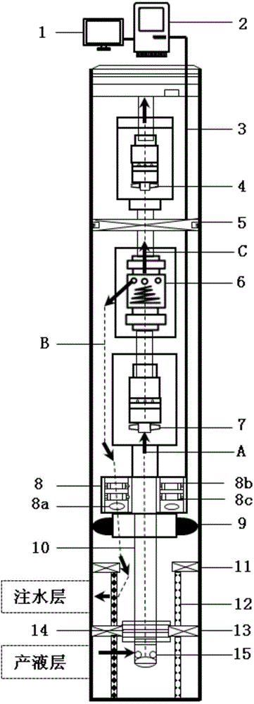
[0004] The present invention aims to solve the technical problem that the flow rate of the large-displacement downhole oil-water separation system cannot be precisely monitored and regulated. It provides a large-displacement downhole oil-water separation annulus measurement and adjustment system. The ground controller controls the opening of the measuring and adjusting instrument of the annulus reinjection channel. During the large displacement oil-water separation annulus reinjection process, the pressure and flow can be monitored in real time, and the reinjection water flow can be adjusted with high precision. To ensure the separation efficiency of the downhole oil-water separation system and the stability of the system working conditions; at the same time, it can also provide accurate liquid production flow and reinjection flow data for reservoir design

Method used


Image

  • High-flow-rate underground oil-water separation and annular space testing and regulating system

Examples


Embodiment Construction

[0015] In order to further understand the invention content, characteristics and effects of the present invention, the following examples are given, and detailed descriptions are as follows in conjunction with the accompanying drawings:

[0016] Such as figure 1 As shown, this embodiment discloses a large-displacement downhole oil-water separation annulus measurement and adjustment system, which mainly includes a large-displacement downhole oil-water separation string and an Injection and production fluid up to 3000m 3 / d large displacement oil-water separation process, by monitoring the pressure and flow of low oily sewage in the annular space reinjection channel, and adjusting the reinjection flow, so as to adjust the ratio of the reinjection flow to the total liquid production flow, that is, the split ratio, Ensure the stability of the downhole oil-water separation system.

[0017] The large-displacement downhole oil-water separation string includes an outer layered isola...


PUM


Abstract

The invention relates to an underground oil-water separating, testing and regulating technology, and discloses a high-flow-rate underground oil-water separation and annular space testing and regulating system, in particular to a system combining an annular space testing and regulating device with a high-flow-rate underground oil-water separation tubular column. The system is divided into a passage for enabling producing liquid on a liquid producing layer to enter an oil-water separator, a passage for reinjecting separated low-oil-content producing waterinto an annular spaceand a passage for lifting high-oil-content producing liquid by the high-flow-rate underground oil-water separation tubular column. The annular space testing and regulating device regulates the split ratio through monitoring the pressure and the flow rate of low-oil-content sewage in the annular space reinjection passage and performing reinjection flow rate regulation, and the stability of the underground oil-water separation system is ensured. The high-flow-rate underground oil-water separation and annular space testing and regulating system has the advantages that the stability of the high-flow-rate underground oil-water separation system can be ensured; the oil-water separation effect is improved; the precision of the testing and regulating system is high; the accurate producing liquid flow rate and rejection flow rate data can be provided for the oil reservoir scheme design; the scheme design accuracy is ensured; the system composition structure is simple; and the requirement of the annular space testing and regulating flow rate measuring range being 50 m<3> / d to 3,000 m<3> / d can be met.

Description

technical field [0001] The invention relates to downhole oil-water separation and measurement and adjustment technology, in particular to a downhole oil-water separation annulus measurement and adjustment system. Background technique [0002] Downhole oil-water separation technology is a technology that separates oil and water in oil wells downhole, reinjects low-oil-produced water into formations, and lifts rich oil-produced fluids to the surface. The downhole oil-water separation system with the separator as the core has three channels, namely, the channel for the liquid in the liquid-producing layer to enter the separator, the channel for the reinjection of the produced water with low oil content after separation, and the lifting channel for the oil-rich produced liquid. According to the change of oil well liquid production rate, water content and water absorption capacity of the water injection layer, adjusting the inlet and outlet flow, pressure and split ratio of the s...

Claims


Application Information

Patent Timeline
IPC IPC(8): E21B43/38E21B43/40E21B43/20
Inventor 王胜王瑶罗昌华杨万有毛庆凯张成富牛贵锋马喜超
Owner CHINA NAT OFFSHORE OIL CORP
Learn More