Power plant boiler high-temperature pipe system macro displacement measurement device and method based on CCD photography

A technology for displacement measurement and power station boilers, which is applied to measurement devices, optical devices, instruments, etc., can solve the problems of inability of remote transmission of measurement data, long cycle, safety monitoring data sorting and analysis, and information feedback lag, etc., to achieve synchronization Good, short-cycle, real-time monitoring and evaluation of the effectiveness of security conditions

Active Publication Date: 2015-10-21
ELECTRIC POWER RES INST OF GUANGDONG POWER GRID +1
View PDF6 Cites 7 Cited by
  • Summary
  • Abstract
  • Description
  • Claims
  • Application Information

AI Technical Summary

Problems solved by technology

[0003] The traditional steam pipeline displacement measurement method is mostly an expansion indicator, which needs to be implemented when the unit is out of operation. Safety monitoring relies on manual data collection and processing, which has a long cycle and poor synchronization. Especially when an emergency occurs in a power plant, data collection cannot be completed continuously in time. It is difficult to monitor and evaluate the safety status of the steam pipeline in a timely manner,

Method used


Image

  • Power plant boiler high-temperature pipe system macro displacement measurement device and method based on CCD photography
  • Power plant boiler high-temperature pipe system macro displacement measurement device and method based on CCD photography
  • Power plant boiler high-temperature pipe system macro displacement measurement device and method based on CCD photography

Examples


Example Embodiment

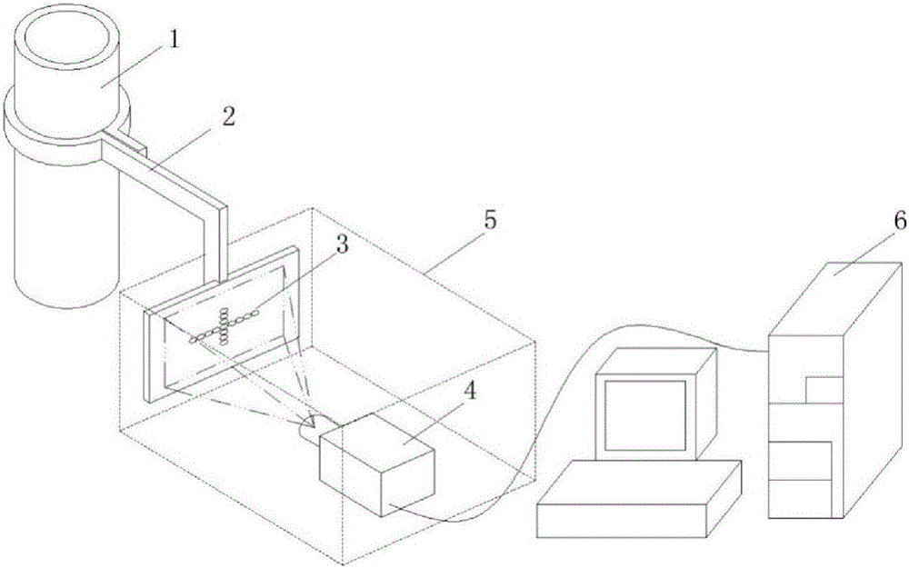
[0040] Such as figure 1 As shown, the embodiment of the macroscopic displacement measuring device for high temperature pipe system based on CCD photography of the present invention includes: fixing assembly 2, cross-shaped LED lamp group 3, CCD camera 4, metal cover 5, image processor 6, 1 is high temperature Pipeline to be tested.

[0041] The hoop of the fixing assembly 2 is fastened to the high-temperature piping system to be tested, one end of the rod-shaped bracket is fixed on the hoop, and the other end of the rod-shaped bracket is fixed with a flat plate. The hoop is connected to the flat plate through the bracket. The cross-shaped LED light group 3 composed of a cross-line array of LED lights is installed in the center of the flat panel. The CCD camera 4 corresponds to the cross-shaped LED light group 3 and is connected to the image processor 6 through a signal cable. The flat panel and the camera of the fixed component are placed In the metal cover 5, the influence of a...


PUM


Abstract

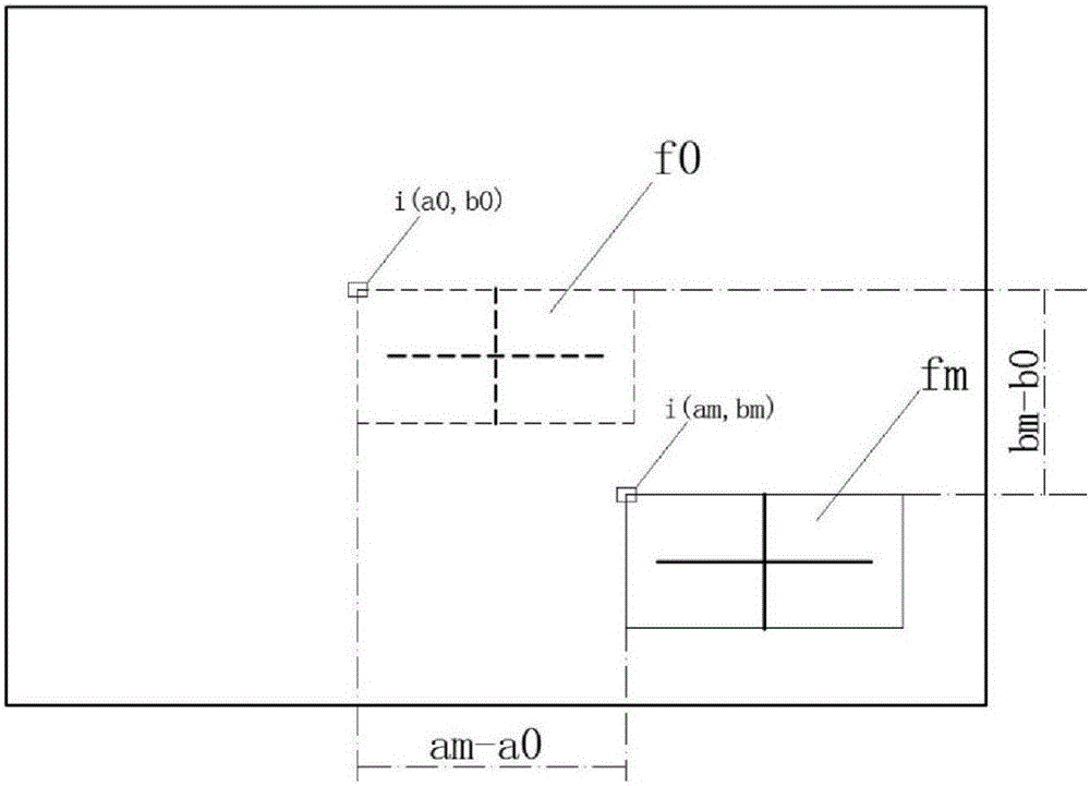
A power plant boiler high-temperature pipe system macro displacement measurement device based on CCD photography comprises a fixing assembly (2), a cross-shaped LED lamp group (3), a CCD camera (4), a lightproof acquisition metal cover (5) and an image processor (6); the fixing assembly (2) is composed of an anchor ear, a support and a flat plate, the support is fixed to the anchor ear, the flat plate is fixed to the support, and the anchor ear is tightly hooped to a high-temperature pipe system to-be-measured pipe (1); LED lamps form a cross curve array, and then the cross curve array is fixed at a central position of the flat plate of the fixing assembly; the CCD camera (4) continuously acquires images formed by the lamp group (3); the lightproof acquisition metal cover (5) covers the LED lamps and the CCD camera; the image processor (6) is connected with the CCD camera through a signal cable and converts the images into a gray value matrix; a certain image matrix is compared with an image matrix recorded at an initial moment, and displacements of a cross curve in the front and rear image matrixes are calculated; and, through combination with magnification and horizontal and vertical interval conditions of CCD pixels, an actual displacement of the lamp group in the object space is calculated. A safety status of a steam pipe can be monitored and evaluated in real time and can be transmitted remotely.

Description

technical field [0001] The invention relates to a macroscopic displacement measuring device of a power plant boiler high-temperature pipe system based on CCD photography (Charge-coupled Device, charge-coupled photography). The invention also relates to a method for measuring the macroscopic displacement of the high-temperature pipe system of the power plant boiler based on the CCD photography by using the above-mentioned device. Background technique [0002] The creep deformation of steam pipes in power plant boilers and the macroscopic instability and displacement of steam pipes caused by the sloshing of supports and hangers are one of the important aspects affecting the safe operation of boilers. Real-time monitoring of high-temperature pipe displacement can reflect the stress and strain inside boiler steam pipes. With the increasingly sophisticated management of equipment safety in thermal power plants, the records of expansion data of high-temperature piping systems such...

Claims


Application Information

Patent Timeline
IPC IPC(8): G01B11/00G01B11/16
Inventor 林介东王伟聂铭钟万里钟力强丁辉许传龙
Owner ELECTRIC POWER RES INST OF GUANGDONG POWER GRID
Why Eureka
Try Eureka