
Locking Cage Mounts

A mounting frame and locking technology, which is applied in the field of optical components, can solve the problems that the connecting rod affects the coaxiality of the optical path, affects the next assembly of the connecting rod, and is easy to scratch the connecting rod, etc., so as to achieve the effect of easy locking and locking Good, avoid scratch effect

Active Publication Date: 2017-05-03
SHANGHAI INST OF OPTICS & FINE MECHANICS CHINESE ACAD OF SCI
View PDF4 Cites 0 Cited by
  • Summary
  • Abstract
  • Description
  • Claims
  • Application Information

AI Technical Summary

Problems solved by technology

In these two solutions, the set screw is directly in contact with the connecting rod. If the force is too large, it is easy to scratch the connecting rod, or cause a small deformation of the connecting rod. Because the connecting rod and the through hole of the connecting rod in the cage plate are usually small in size The clearance fit of the connecting rod, the burr generated by scratching the connecting rod may affect the next assembly of the connecting rod, and the small deformation of the connecting rod may affect the coaxiality of the optical path

Method used


Image

  • Locking Cage Mounts
  • Locking Cage Mounts
  • Locking Cage Mounts

Examples


Embodiment Construction

[0027] The present invention will be described in detail below in conjunction with the accompanying drawings and embodiments, but the protection scope of the present invention should not be limited thereto.

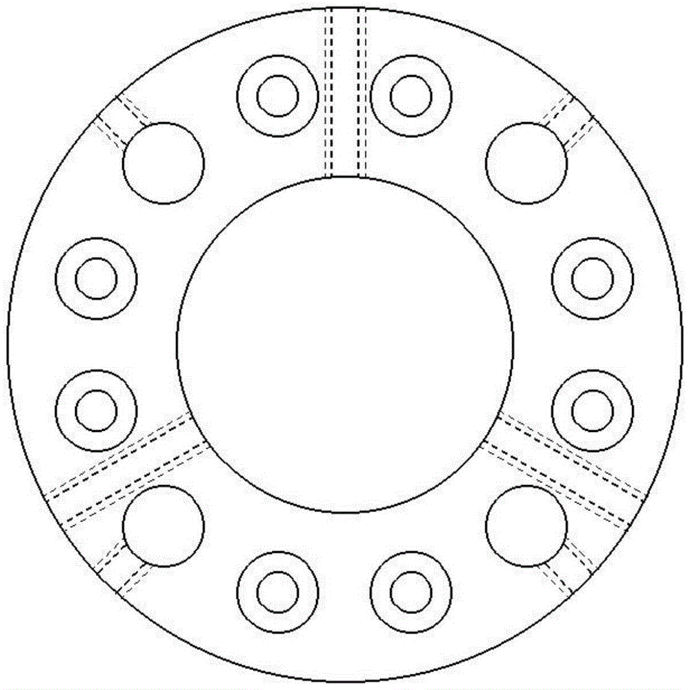
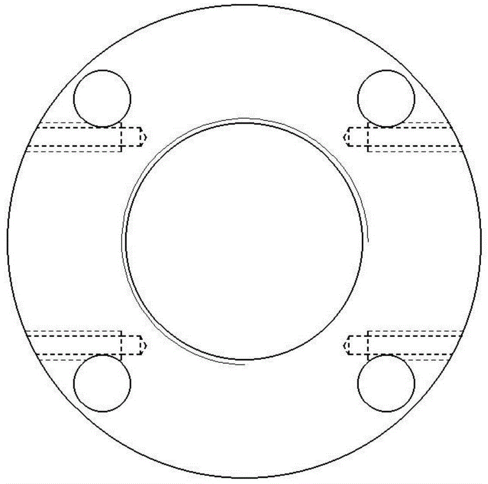
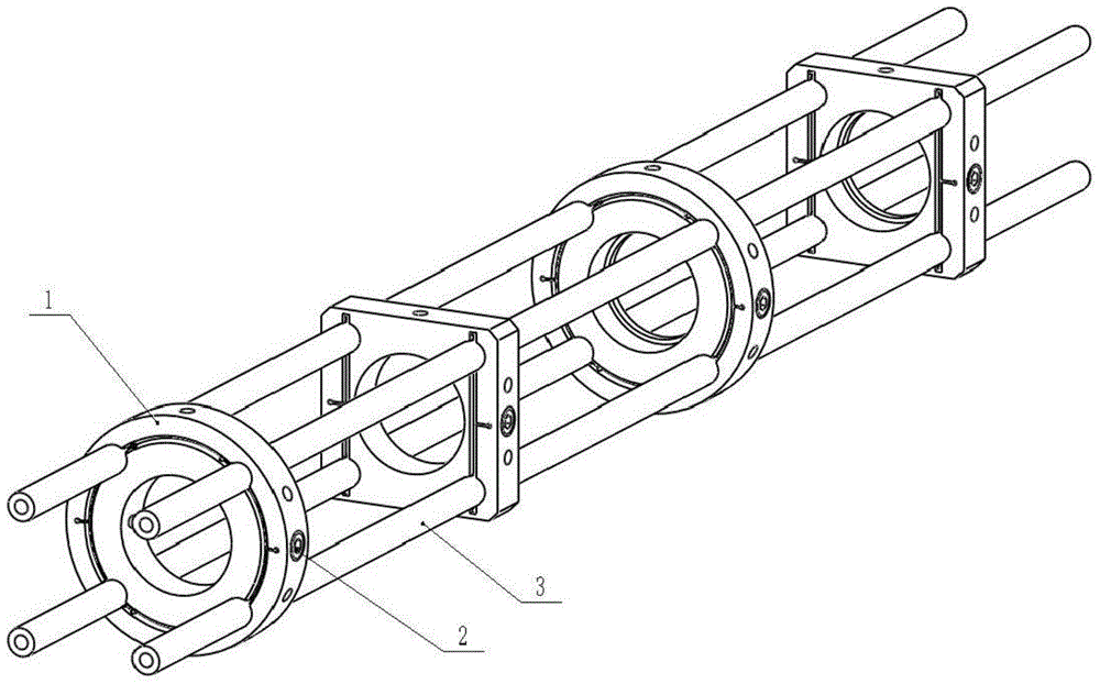
[0028] see first image 3 , and see in conjunction with Figure 4 , 5 , 6, 7, 8, 9, 10, 11, as can be seen from the figure, the locking cage mounting frame of the present invention includes: a plurality of cage plates 1, a plurality of screws 2, and four connecting rods 3.

[0029] The cage plate 1 has a central hole 101 and four connecting rod through holes 102 evenly distributed around it, and the axes of the four connecting rod through holes 102 are parallel to the central axis of the central hole 101. The two connecting rod through holes 102 on both lateral sides of the cage plate 1 are connected through a through groove 103, and the connection between the connecting rod through holes 102 and the through groove 103 has a first semicircular opening 109, and the first...


PUM


Abstract

The invention relates to a locking cage type mounting rack. The locking cage type mounting rack comprises a plurality of cage plates and four connecting rods. According to the locking cage type mounting rack of the invention, screws for locking the connecting rods do not directly contact with the connecting rods, while, the screws are screwed, so that the gaps of circular arc-shaped through grooves of the cage plates can be decreased, and therefore, lateral squeezing can be generated for the connecting rods, and the connecting rods can be locked. Since a locking mode adopted in the invention is surface contact, the locking cage type mounting rack provided by the invention has the advantages of simple operation and excellent locking effects. With the locking cage type mounting rack adopted, the scratch and deformation of the connecting rods can be avoided, and quick installation and disassembly of the cage plates can be realized. The locking cage type mounting rack can be applied to vacuum environment.

Description

technical field [0001] The present invention relates to optical components, in particular to a locking cage mount. It is mainly used in the installation and adjustment of optical precision mechanical systems. Background technique [0002] Existing optical element adjustment mounts often have complex structures and occupy a large area. When arranging the optical path along the optical axis, each optical element needs to be adjusted individually, which is time-consuming and labor-intensive, and the operation is difficult. [0003] In order to solve the above problems, U.S. Patent U.S.Number 5828502 proposes a cage mounting system, which consists of a series of precision-processed mechanical modules, which can accurately and flexibly construct an optical precision mechanical system. Among them, the cage mounting frame is mainly used to build the basic structure of the system and carry optical components. Its main advantages are: simple structure, easy to install and disassemb...

Claims


Application Information

Patent Timeline
Patent Type & Authority Patents(China)
IPC IPC(8): G02B7/00G01M11/04
CPCG02B7/00
Inventor 江梦春朱健强
Owner SHANGHAI INST OF OPTICS & FINE MECHANICS CHINESE ACAD OF SCI
Learn More