Cooling device of transformer

A heat dissipation device and transformer technology, applied in the direction of transformer/inductor cooling, etc., can solve the problems of unable to accelerate the heat dissipation of the radiator, large loss of fan motor, low cooling efficiency, etc., achieve low cost of use, small equipment loss, and good heat dissipation effect Effect

Inactive Publication Date: 2015-10-21
李斌
View PDF6 Cites 3 Cited by
  • Summary
  • Abstract
  • Description
  • Claims
  • Application Information

AI Technical Summary

Problems solved by technology

The oil-immersed self-cooling type uses the natural convection of the oil to bring the heat to the tank wall and the heat dissipation pipe, and then relies on the convection conduction of the air to dissipate the heat. This cooling method usually does not have special cooling equipment; however, this cooling method cools The speed is slow and the cooling efficiency is not high, especially during the high temperature and high load period in summer, the temperature o

Method used


Image

  • Cooling device of transformer
  • Cooling device of transformer

Examples


Example Embodiment

[0018] The realization of the objectives of the present invention, functional characteristics and beneficial effects will be further described below in conjunction with specific embodiments and drawings.

[0019] The technical solutions of the present invention will be further described in detail below with reference to the accompanying drawings and specific embodiments, so that those skilled in the art can better understand and implement the present invention, but the examples given are not intended to limit the present invention. .

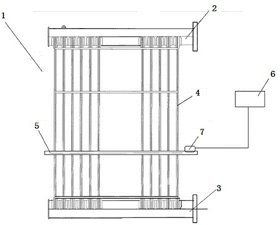
[0020] Such as Figure 1-2 As shown, the heat dissipation device of the transformer in the embodiment of the present invention includes a radiator body 1. The radiator body 1 includes an oil inlet pipe 2, an oil return pipe 3, a number of radiating fins 4, and a body fixing rib 5, and the oil return pipe 3 is located on the oil inlet pipe 2. Below, a number of radiating fins 4 are arranged in sequence between the oil inlet pipe 2 and the oil return ...


PUM


Abstract

The invention discloses a cooling device of a transformer. The cooling device comprises a radiator body, and the radiator body comprises an oil inlet pipe, an oil return pipe, a plurality of cooling fins and a body fixing rib. The oil return pipe is located below the oil inlet pipe, the cooling fins are sequentially arranged between the oil inlet pipe and the oil return pipe and are of a hollow structure, and the cooling fins are connected and communicated with the oil inlet pipe and the oil return pipe. The radiator body further comprises a water pipe set for providing cooling water for the surfaces of the cooling fins, a water supply controller and a temperature inductor on the body fixing rib, and the temperature inductor is connected with the water supply controller. The water supply controller controls water paths of the water pipe set to be connected and disconnected. The temperature inductor transmits signals to the water supply controller. When the temperature, measured by the temperature inductor, around the cooling fins is high, for example, the temperature is about 60 DEG C, the water supply controller opens a water supply channel to carry out water spraying cooling on the cooling fins. Automatic water spraying cooling can be achieved, cooling speed is high, and efficiency is high.

Description

technical field [0001] The invention relates to a cooling device for a transformer, which belongs to the technical field of electric equipment. Background technique [0002] During the operation of the transformer, due to the existence of iron loss and copper loss, these losses will be converted into heat energy and radiated outward, which will cause the transformer to continue to heat up and the temperature will rise. If the heat dissipation of the transformer is not good, the temperature of the transformer will rise. If the temperature rise exceeds the allowable level of the transformer, the service life of the transformer will be reduced, and the transformer will be damaged if it is serious. Therefore, in order to ensure good heat dissipation of large transformers, certain cooling methods must be used to take away the heat generated in the transformer. [0003] The structure of the current oil-immersed transformer radiator includes an oil inlet pipe, an oil return pipe, ...

Claims


Application Information

Patent Timeline
IPC IPC(8): H01F27/16H01F27/12
Inventor 李斌鲍荣伟
Owner 李斌
Why Eureka
Try Eureka