Supercharge Your Innovation With Domain-Expert AI Agents!

Web cooperative caching system and method

A caching system and caching technology, applied in transmission systems, electrical components, etc., can solve the problems of large system communication bandwidth overhead, unsatisfactory, and increased concurrent access, so as to reduce system communication bandwidth overhead and reduce the possibility of failure. the effect of reducing terminal access delay

Active Publication Date: 2015-10-21
INST OF COMPUTING TECH CHINESE ACAD OF SCI
View PDF3 Cites 10 Cited by
  • Summary
  • Abstract
  • Description
  • Claims
  • Application Information

AI Technical Summary

Problems solved by technology

However, this solution is still not ideal, and there are at least the following problems: 1. In actual application scenarios, such as large shopping malls or supermarkets, there will be a sharp increase in the number of concurrent accesses of the entire system terminal during certain periods of time
At this time, the interaction between the AP and the cache controller in this solution tends to become extremely frequent, and the degree of network congestion intensifies
If the concurrent processing capability of the cache controller is not enough to withstand this amount of concurrency, it is very likely to cause the cache controller to crash and fail, which will greatly reduce the efficiency of the entire system; 2. The physical distance between the AP and the cache controller in the actual deployment of the system They are often far apart, and the communication delay between them will increase with the increase of the distance, while the distance between APs is often relatively short, so the communication delay between the AP and the cache controller often becomes the delay of the entire terminal request. The main bottleneck
[0008] Therefore, in the WLAN scenario with a large number of APs, the existing web caching system deployment method has the disadvantages of easily forming a single point of failure, low resource utilization rate, terminal access delay bottleneck, and high system communication bandwidth overhead.

Method used


Image

  • Web cooperative caching system and method
  • Web cooperative caching system and method
  • Web cooperative caching system and method

Examples


Embodiment Construction

[0033] The present invention will be further described below in conjunction with the accompanying drawings and specific embodiments.

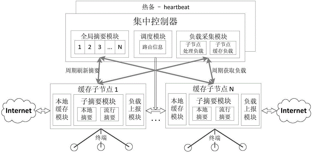
[0034] figure 1 A schematic diagram of the architecture of the Web collaborative caching system according to an embodiment of the present invention is shown, including a centralized controller serving as a control plane and at least two caching sub-nodes in the same local area network. In a WLAN, each cache subnode may be an AP in the WLAN. Wherein, for each cache sub-node, other cache sub-nodes belonging to the same centralized controller are called adjacent nodes of the cache sub-node.

[0035]According to an embodiment of the present invention, all cache subnodes have the same structure, and each cache subnode provides cache services for terminals directly connected to it. The cache sub-node includes a local cache, a sub-summary module, and a load reporting module. Among them, the local cache is used to store and maintain the Web objects ...


PUM


Abstract

The invention provides a Web cooperative cashing system. The system comprises one integrated controller and two or more than two cache child nodes; the cache digests of the cache child nodes comprise local digests and popular digests; the popular digests are used for maintaining the routing information of all Web objects acquired by the cache child nodes from the adjacent nodes; the integrated controller comprises an overall digest, which is used for preserving the local digest information of all cache child nodes that belong to the integrated controller. The invention further provides a method used for the Web cooperative cashing system. According to the technical scheme adopted by the invention, the Web cooperative cashing system can lighten the load of the integrated controller, reduce the probability that the integrated controller is invalid as a single point, effectively improve the effective utilization rate of the system resources, reduce terminal access delay and system communication bandwidth cost and significantly improve the quality of network service of users.

Description

technical field [0001] The present invention relates to the field of computer network transmission control, in particular, the present invention relates to a system and method for web cooperative caching. Background technique [0002] AP (Access Point, wireless access point) is equivalent to a bridge connecting the wired network and the wireless network, and its main function is to provide wireless terminals with access to the Ethernet. Many APs are deployed in typical campus networks such as enterprises and shopping malls, and a large number of mobile terminals access the Internet through these APs. The access of a large number of WLAN terminals may easily cause congestion of the uplink aggregation link, increase network access delay, and cause a decline in TCP throughput. In order to improve network service performance, a common solution is to use network caching technology for web acceleration. [0003] The network caching technology utilizes the locality principle of W...

Claims


Application Information

Patent Timeline
Patent Type & Authority Applications(China)
IPC IPC(8): H04L29/08
CPCH04L67/1095H04L67/568
Inventor 王亚坤张广兴余显谢高岗
Owner INST OF COMPUTING TECH CHINESE ACAD OF SCI
Features
  • R&D
  • Intellectual Property
  • Life Sciences
  • Materials
  • Tech Scout
  • Unparalleled Data Quality
  • Higher Quality Content
  • 60% Fewer Hallucinations
Learn More