
Battery housing

A battery casing and battery technology, applied in the field of cooling systems, can solve the problems of increasing the number of potential failure points in the connection system, increasing the overall cost of the battery casing, etc.

Inactive Publication Date: 2015-10-21
FASTER FASTER
View PDF3 Cites 19 Cited by
  • Summary
  • Abstract
  • Description
  • Claims
  • Application Information

AI Technical Summary

Problems solved by technology

However, making electrical contacts at both ends of each battery cell increases the number of potential failure points in the connection system and increases the overall cost of the battery housing

Method used


Image

  • Battery housing
  • Battery housing
  • Battery housing

Examples


Embodiment Construction

[0019] Overview of the battery case

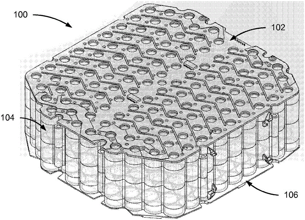
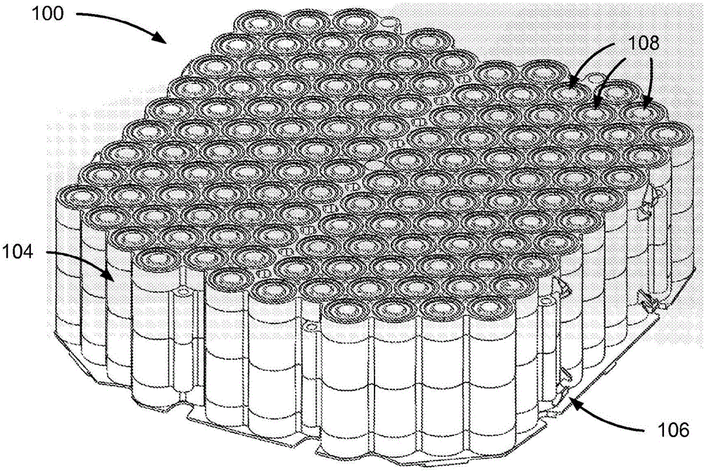
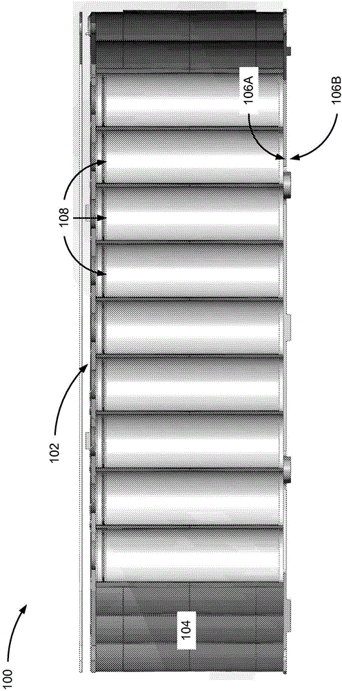
[0020] Figure 1A is a perspective view of a battery case 100 according to one embodiment. The battery housing 100 includes a circuit board 102 , a frame structure 104 and a heat sink 106 . Figure 1B is a perspective view of the battery case 100 with the circuit board 102 removed. like Figure 1B As shown, frame structure 104 contains compartments for battery cells 108 . Figure 1C is a side cross-sectional view of the battery housing 100 showing the battery cells 108 inside the frame structure 104 .

[0021] The circuit board 102 contains circuitry for electrically connecting the battery cells 108 . In one embodiment, the circuit board 102 connects the battery cells 108 in a parallel-series configuration. In a parallel-series configuration, the battery cells 108 may be divided into groups of cells, where the cells in each group are connected in parallel, and the groups are connected in series. In other embodiments, the circuit boa...


PUM


Abstract

A battery housing includes a heat spreader, a thermal interface that contacts a surface of the heat spreader, and a battery frame that is configured to hold a plurality of battery cells. When a battery cell is inserted into the battery frame, the thermal interface contacts the cell at the same end as the cell's negative terminal. As a result, the thermal interface allows heat to be transferred between the battery cell and the heat spreader. It is advantageous to make a thermal connection at the end with the negative terminal because the internal jelly roll structure of the battery cell causes the cell to have a higher thermal conductivity at its negative terminal.

Description

technical field [0001] The present disclosure relates generally to battery housings, and in particular to electrical interconnects between battery cells in battery housings, thermally insulating battery cells in battery housings, and for battery housings The cooling system of the battery cells in. Background technique [0002] The battery housing typically includes electrical conductors that connect the battery cells in a series and / or parallel configuration to form a battery system with a desired energy capacity and output voltage. On cylindrical cells, the positive and negative terminals are positioned at opposite ends of the cell. Typically, electrical contacts are made at both ends of each battery cell in the battery housing so that both the positive and negative terminals are directly connected to the conductors. However, making electrical contacts at both ends of each battery cell increases the number of potential failure points in the connection system and increases...

Claims


Application Information

Patent Timeline
IPC IPC(8): H01M2/00H01M50/213H01M50/509H01M50/51H01M50/512H01M50/514H01M50/519H01M50/569
CPCH01M2/206H01M2/1077H01M2/1094H01M10/0525H01M10/5053H01M10/6554Y02E60/10H01M50/24H01M50/519H01M50/514H01M50/213H01M50/509H01M50/512H01M50/51H01M50/569
Inventor R·W·斯维内D·多瑞斯泰恩J·W·桑德C·C·布莱恩
Owner FASTER FASTER
Learn More