Subsoiling and smashing and ridging machine

A powder ridge machine and powder ridge technology, applied in the direction of harvesters, crop processors, agricultural machinery and implements, etc., can solve problems such as damage to the driving mechanism, high bearing seat height, and manufacturing difficulties.

Inactive Publication Date: 2015-10-28
GUANGXI WUFENG MACHINERY CO LTD
View PDF9 Cites 6 Cited by
  • Summary
  • Abstract
  • Description
  • Claims
  • Application Information

AI Technical Summary

Problems solved by technology

[0004] When the powder ridge device is used to loosen the powder ridge, the auger rod will be subjected to axial force and radial force, and the auger rod is connected to the transmission shaft of the transmission system, so the lower end of the transmission shaft will also be subject to greater force. Large axial force and radial force, therefore, the general transmission shaft is installed on the fan box through the bearing, the powder box is also used to install the transmission system, and forms a lubricating oil tank, so that it will be on the upper end of the powder box and the lower end are provided with bearing housings respectively, and the existing bearing housings and the powder ridge box have an integrated structure, so it is difficult to manufacture and the cost is high
[0005] In addition, in order to increase the number of supporting points for the transmission shaft and improve the rigidity of the transmission shaft, multiple bearings are usually installed, and sometimes multiple bearings are installed on the same bearing seat. Then, the height of this bearing seat is relatively large, and its strength hard to guarantee
[0006] Most of the cutting tools of the existing tiller are auger rods. During the loosening process, the rotation of the auger rod will be subjected to the reverse resistance of the land. Therefore, power output often occurs, but the auger rod is stuck. It cannot rotate or the speed of rotation is slowed down. In this way, not only can the loose tillage be continued or the effect of loose tillage will be poor, but also the life of the driving mechanism will be shortened or the driving mechanism will be directly damaged.

Method used


Image

  • Subsoiling and smashing and ridging machine
  • Subsoiling and smashing and ridging machine
  • Subsoiling and smashing and ridging machine

Examples


Embodiment 1

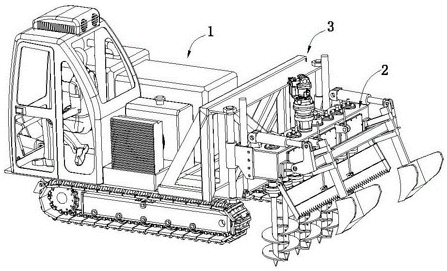
[0057] Such as figure 1 and figure 2 As shown, the loose tillage powder ridge machine includes a body 1, a powder ridge device 2, and a connecting device 32.

[0058] Such as figure 2 As shown, the body 1 includes a traveling mechanism 11 , a frame 12 , a diesel engine assembly 13 , a hydraulic oil tank 14 , a cooler 15 and a cab 16 .

[0059] Such as Figure 3 to Figure 8 As shown, the running mechanism 11 includes two opposite crawler belt assemblies, and the crawler belt assembly includes a wheel frame 111, a driving wheel 112, a driven wheel 113, a lower guide wheel 114, an upper guide wheel 115, a crawler belt 116 and a travel drive.

[0060] Such as Figure 7 and Figure 8 As shown, the wheel frame 111 includes a wheel frame body 1111 and a wheel frame connecting ear 1112 . The wheel frame connecting ear 1112 is connected to the front end of the wheel frame body 1111 . The rear end of the wheel frame body 1111 is provided with a driven wheel accommodating groove...

Embodiment 2

[0141] Compared with Embodiment 1, this embodiment has the same structure except for the connecting device. In this example, if Figure 22 to Figure 24 As shown, the connecting device 3 includes two linkage mechanisms and a connecting rod 310a connected to the two linkage mechanisms. The connecting rod mechanism includes a connecting rod seat 30a, a first connecting rod 31a, a second connecting rod 32a, a third connecting rod 33a, a fourth connecting rod 34a and a driving cylinder 35a. The connecting rod base 30a is fixed on the supporting platform; the lower end of the first connecting rod 31a is hinged on the rear end of the connecting rod base 30a, and one end of the second connecting rod 32a is hinged on the position below the middle part of the first connecting rod 31a, and the second connecting rod The other end of 32a is hinged on the first connecting ear 29; one end of the third connecting rod 33a is hinged on the upper end of the first connecting rod 31a, the other e...


PUM


Abstract

The invention discloses a subsoiling and smashing machine. The subsoiling and smashing machine comprises a machine body, a smashing and ridging device, a connecting device, a ditching device, a leveling device and a device for returning straws to a field; the smashing and ridging device comprises a smashing and ridging box; the smashing and ridging box comprises a bottom plate, a side plate and a top plate; lower bearing bases are mounted on the bottom plate; a rib plate is welded between the lower bearing bases; a lubricating oil channel is arranged between the rib plate and the bottom plate; upper bearing bases are mounted on the top plate; and the lower bearing bases are arranged on the upper bearing bases. According to the subsoiling and smashing and ridging machine, the strength of the lower bearing bases can be improved; a plurality of bearings are conveniently mounted on places which with great stress, and less bearings are mounted on places with little stress; so that the rigidity and the transmission stability of a transmission shaft are improved, and the cost can be reduce; the rib plate is conveniently welded; and the lubricating oil is guaranteed to smoothly flow in the smashing and ridging box, thereby improving the lubricating effect.

Description

technical field [0001] The invention relates to a plowing powder ridge machine. Background technique [0002] The main function of loose plowing powder ridge machine is to loosen and crush the land. In the past, loose plowing and crushing were realized by hoes or cattle plowing, but no matter which of the above-mentioned traditional methods, it is not only laborious but also inefficient. Therefore, For a large area of ​​land that needs to be plowed and crushed, the traditional method has been unable to adapt. For this reason, the current automatic plowing machine has appeared. For example, the application number is 201020514808.9, the application date is 2010.9.3, and the authorization announcement date is 2011 Disclosed in the patent literature on July 20, 2010 is a kind of rotary grinding type deep plowing powder ridge multifunctional machine. Also disclose a kind of spiral type subsoiling cultivator in the patent document that the patent No. is ZL201420551437.X. [0003...

Claims


Application Information

Patent Timeline
IPC IPC(8): A01B49/02A01B49/04A01D82/00
Inventor 李深文
Owner GUANGXI WUFENG MACHINERY CO LTD
Why Eureka
Try Eureka