
Series-parallel type five-freedom-degree bionic shoulder joint linked with shoulder blade

A degree of freedom, hybrid technology, applied in manipulators, manufacturing tools, joints, etc., can solve problems such as structural form, low bionic level of motion characteristics, gap in functional characteristics of human shoulder joints, and inability to achieve

Inactive Publication Date: 2015-10-28
YANSHAN UNIV
View PDF8 Cites 6 Cited by
  • Summary
  • Abstract
  • Description
  • Claims
  • Application Information

AI Technical Summary

Problems solved by technology

In 2005, the 3-DOF bionic shoulder joint (the Cybernetic Shoulder) designed by the University of Tokyo in Japan considered the effect of the human body's scapula support on the movement of the large arm. However, its working space center is located on the side of the human body, which is different from the human body's large arm The actual situation of the movement does not match. Nearly half of the working space at the back of the coronal plane of the human body is free, and the area of ​​the front of the coronal front of the human body where the adduction and swing of the upper arm exceeds 90 degrees cannot be realized.
Therefore, the existing parallel bionic shoulder joints of humanoid robots have a low bionic level in terms of structural form and motion characteristics, and have a large gap with the functional characteristics of human shoulder joints.

Method used


Image

  • Series-parallel type five-freedom-degree bionic shoulder joint linked with shoulder blade
  • Series-parallel type five-freedom-degree bionic shoulder joint linked with shoulder blade
  • Series-parallel type five-freedom-degree bionic shoulder joint linked with shoulder blade

Examples


Embodiment Construction

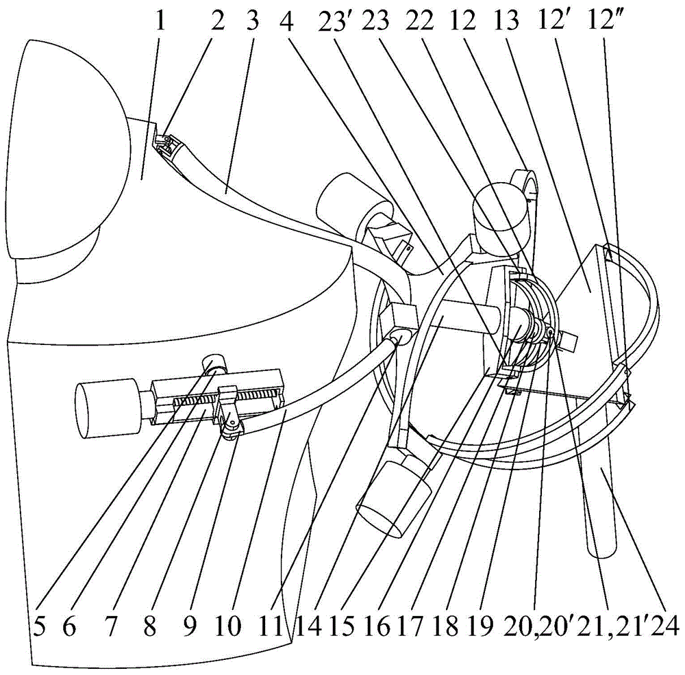
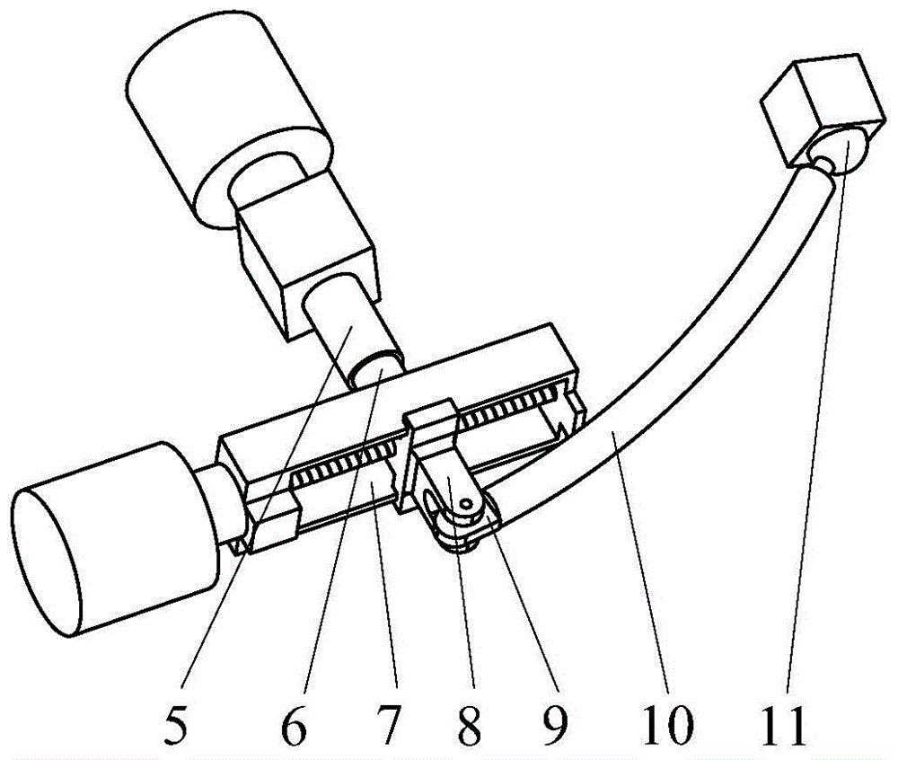
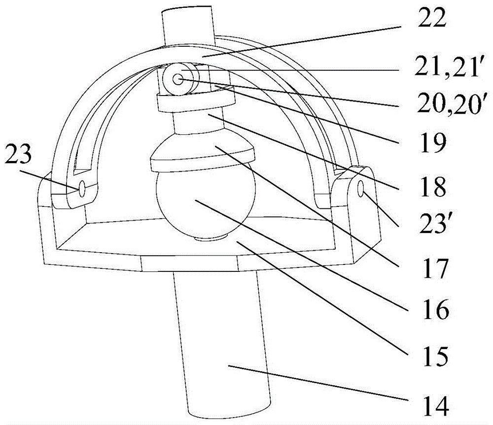
[0023] exist figure 1 In the schematic diagram of the mixed-type five-degree-of-freedom bionic shoulder joint with scapula linkage shown, the present invention is mainly composed of four parts: RPRS+U two-degree-of-freedom series mechanism, 3-RRR three-degree-of-freedom spherical parallel mechanism, and a large working space Spherical hinge and offset output unit; one end of the S-shaped connecting rod 3 in the RPRS+U two-degree-of-freedom series mechanism is connected to the bionic frame 1 through the Hooke hinge 2, and the other end of the S-shaped connecting rod is connected to the intermediate dynamic Platform 4 is fixedly connected, such as figure 2 As shown, one end of the output shaft 6 in the RPRS motion branch chain is connected to the bionic frame through the active rotating pair 5, the other end of the output shaft is fixedly connected to the linear guide rail 7, and the motor driving the active rotating pair is fixedly connected to the bionic frame; The active sl...


PUM


Abstract

Disclosed is a series-parallel type five-freedom-degree bionic shoulder joint linked with a shoulder blade. An S-shaped connecting rod in an RPRS+U two-freedom-degree series mechanism of the shoulder joint is connected with a bionic rack and an intermediate movable platform. An output shaft in an RPRS movement branch chain is connected with the bionic rack and a linear guide rail, a driving sliding block is arranged on a lead screw of the linear guide rail and is connected with a driven rod, and the driven rod is connected with the intermediate movable platform. Three rotary branch chains of the same structure in a 3-RRR three-freedom-degree spherical parallel mechanism are connected with the intermediate movable platform and a tail-end movable platform. A spherical hinge with the large work space is connected with the intermediate movable platform and a bias output unit. The bias output unit comprises a supporting rod, a double-lug support, a ball head, a movable ball socket, an output rod, rotary supports, supporting pin shafts, a supporting roller, U-shaped shifting forks and a pin shaft. The bias output unit is a bias output rod. By the adoption of the bionic shoulder joint, five-freedom-degree movement of the bias output rod can be achieved, and the state of the bionic shoulder joint is close to the actual state of the human body shoulder joint to the maximum degree in the aspects of the structure, the movement and functions.

Description

technical field [0001] The invention relates to the field of humanoid robot joints, in particular to a hybrid bionic shoulder joint. Background technique [0002] As one of the most active branches in the field of robotics, the development level of humanoid robots is an important symbol of a country's high-tech comprehensive strength. At present, the research aimed at realizing the general (maneuvering, operating) functions of humanoids has come to an end. Smart Bionic. The mechanical body is the basic framework of humanoid robots, which directly determines the performance of humanoid robots and restricts the potential of humanoid robot control and intelligent development in the future. It is the primary task of designing humanoid robots. In the mechanical body of the humanoid robot, each joint of the humanoid robot is the most critical part. The existing joint mechanisms of various humanoid robots are mostly in series configuration, that is, two or three single rotating ...

Claims


Application Information

Patent Timeline
IPC IPC(8): B25J17/00
Inventor 周玉林杨龙褚宏鹏孙通帅
Owner YANSHAN UNIV
Learn More