#-shaped front sub frame

A front subframe, well-shaped technology, applied in the field of design and automobile manufacturing, can solve the problems of difficulty in increasing the Z-direction stiffness, stress concentration at the welding seam, excessive weight, etc., to achieve improved strength and stiffness, good forming performance, Weight reduction effect

Pending Publication Date: 2019-04-05
ZHEJIANG TUOWEI AUTOMOBILE PARTS CO LTD
View PDF0 Cites 2 Cited by
  • Summary
  • Abstract
  • Description
  • Claims
  • Application Information

AI Technical Summary

Problems solved by technology

[0003] Generally, the front beam, rear beam, and longitudinal beam of the frame-type subframe are welded by two stamping parts. This structure will form more welds, and the welds are prone to stress concentration, cracking, and the weight exceeds the standard.
The suspension installation bracket is hung on the rear beam, and it is difficult to increase the Z-direction stiffness of the suspension installation point. Due to the above restrictions, the load of the car will match the weight of the vehicle due to the cruising range, and the matching needs to be adjusted to a certain extent. , so the application of the frame-type sub-frame in the prior art is further limited in the field of automobile technology, and in order to cope with the adjustment of the aforementioned parameter requirements, a simpler part structure must be further adopted, and the overall assembly requirements should be easy and convenient for production. Can't meet demand

Method used


Image

  • #-shaped front sub frame
  • #-shaped front sub frame
  • #-shaped front sub frame

Examples


Embodiment Construction

[0039] Below by embodiment, in conjunction with accompanying drawing, the technical scheme of the present invention is as preferred specific description:

[0040]It should be noted that the words "front", "rear", "left", "right", "upper" and "lower" used in the following description refer to the directions in the drawings, and the words "inner" and "outer "respectively refer to towards or away from. If it is to describe the structure of the shell cavity, it is to describe the inside and outside of the shell, the direction of the geometric center of the invention or its specific components. The connection method specified in this embodiment is generally Welded connections, bolt or screw connections, snap-fit ​​connections, snap-fit ​​connections, etc. of the prior art are all prior technologies well known to those skilled in the art.

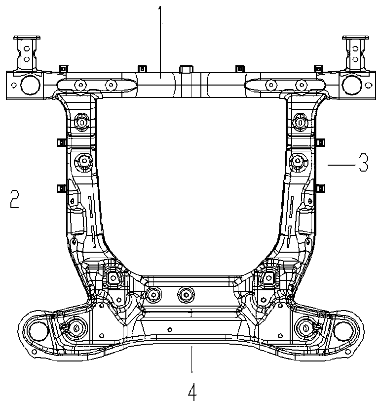
[0041] Such as figure 1 The well-shaped front auxiliary frame shown includes front beam (1), left side beam (2), right side beam (3), and rear ...


PUM


Abstract

The invention relates to the field of automobile manufacturing and design, specifically to a #-shaped front sub frame. The rigidity of each mounting point is higher so that the controllability of thewhole automobile is improved. The sub frame and an automobile body are flexibly connected with each other through a bushing; and therefore, the shock from a pavement is effectively blocked, and the comfort of the whole automobile is improved. The #-shaped front sub frame comprises a front cross beam, a left side beam, a right side beam and a rear cross beam; a left side beam and a right side beamare correspondingly arranged on the two sides of the front cross beam downwards; the tail end of the left side beam and the tail end of the right side beam are inserted into the tops of the head and the top of the rear cross beam to be integrally connected to form a square shape or # shape, wherein the left side beam and the right side beam have same structures and acting as mirror images of eachother; the left side beam and the right side beam comprise side beam upper plates and side beam lower plates; the side beam upper plates and the side beam lower plates are arranged to cover each otherin the up-and-down direction; after the side beam upper plates and the side beam lower plates are arranged to cover each other in the up-and-down direction, side beam cavities are formed inside; therear cross beam comprises a rear cross beam upper sheet and a rear cross beam lower sheet; the rear cross beam upper sheet and the rear cross beam lower sheet are connected with each other in a covering manner; a rear cross beam cavity is formed inside; and connecting ports are formed in positions, matched with the left side beam and the right side beam, on the rear cross beam.

Description

technical field [0001] The invention relates to the fields of automobile manufacture and design, in particular to a well-shaped front auxiliary frame. Background technique [0002] With the rapid development of automobiles in China, the competition in the automobile industry is also increasing. Energy disputes are the most cutting-edge technical issues. Therefore, various new energy vehicles have emerged. They do not need to rely solely on gasoline and have zero emissions. , which is also the direction of future automobile development. Under the existing technical structure, it is necessary to change the subframe structure of the existing fuel locomotive into an electric vehicle for use. Under the existing technology, the subframe structure is a part of the chassis suspension system of the automobile. At present The common types of subframes are full frame type ("mouth" type), half frame type ("H" type) and Yuanbao beam. The sub-frame has installation positions for control ...

Claims


Application Information

Patent Timeline
Patent Type & Authority Applications(China)
IPC IPC(8): B62D21/02
CPCB62D21/02
Inventor 刘黎明翁盛锋杨天洪李少安徐晓华陈峰
Owner ZHEJIANG TUOWEI AUTOMOBILE PARTS CO LTD
Why Eureka
Try Eureka