
A compound and high-efficiency filter press device in electrolytic zinc process

A technology of electrolytic zinc and process, which is applied to the improvement of process efficiency, photographic process, photographic auxiliary process, etc. It can solve the problems that the working efficiency of the filter press cannot be fully utilized, the resistance of the press filter is increased, and the flow rate of the filter liquid is small. , to achieve the effect of improving the dissolution and heating effect, no steam noise, and reducing the dosage

Active Publication Date: 2016-09-07
湖南轩华锌业有限公司
View PDF2 Cites 0 Cited by
  • Summary
  • Abstract
  • Description
  • Claims
  • Application Information

AI Technical Summary

Problems solved by technology

[0007] However, in the filter press operation, the existing centrifugal pumps cannot automatically adapt to such a process to achieve an ideal working state of high efficiency and high quality
Generally, when a centrifugal pump performs filter press operation, the head of the filter press is low in the early stage, but the flow rate is large, so that the motor is in an overload state, and it is easy to burn the motor; The flow rate decreases rapidly. At this time, although the motor works in a light-load and low-power state, the filter press efficiency is very low; although the filter press pump has the maximum head output state, due to the small flow rate of the filter press fluid, the filter press cannot be fully utilized. Work performance and improve work efficiency

Method used


Image

  • A compound and high-efficiency filter press device in electrolytic zinc process
  • A compound and high-efficiency filter press device in electrolytic zinc process
  • A compound and high-efficiency filter press device in electrolytic zinc process

Examples


Embodiment Construction

[0023] The present invention will now be further described in detail with reference to the accompanying drawings.

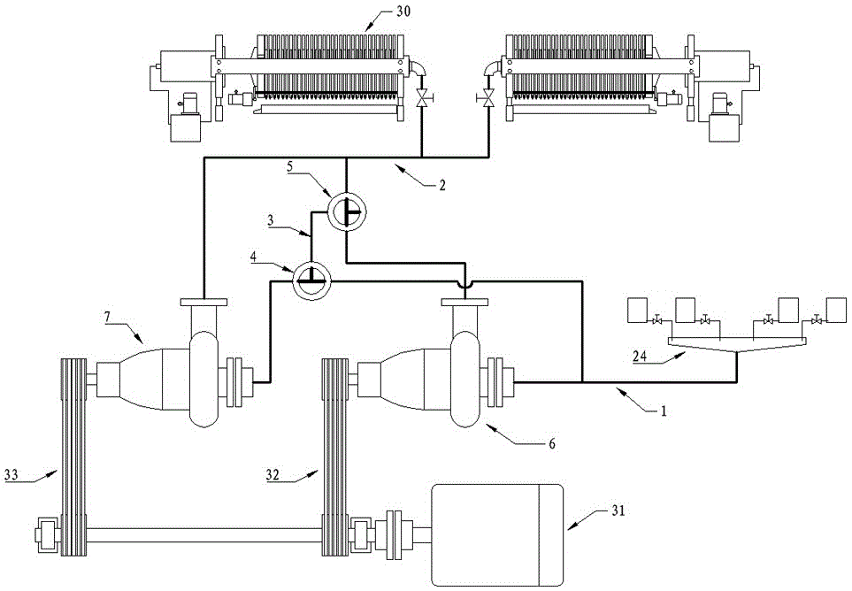
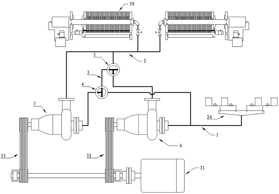
[0024] like figure 1 and figure 2 The combination and high-efficiency filter press device in the electrolytic zinc process shown includes an inlet pipe 1, two centrifugal pumps (6, 7), an outlet pipe 2 and two filter presses 30, and the two centrifugal pumps (6, 7) are composed of The same motor 31 is driven by a belt (32, 33); the inlet pipe 1 is branched into two pipes, one pipe is connected to the outlet pipe 2 through the three-way cock 4 and the centrifugal pump 7, and the other pipe is passed through another centrifugal pump 6 and another The three-way cock 5 is connected to the outlet pipe 2; the two three-way cocks 4 and 5 are connected up and down through the intermediate pipe 3; the inlet pipe 1 is connected to the zinc solution flow tank 24, and the flow tank 24 has an inverted conical bottom structure; two filter presses After the machine 30 is con...


PUM


Abstract

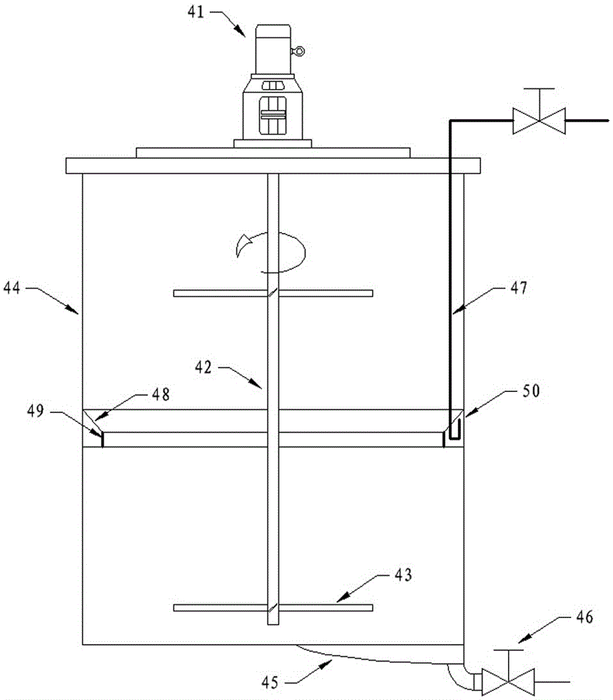
The invention discloses a compounding and high-efficiency filter press device in the electrolytic zinc process, which includes an inlet pipe, an outlet pipe, two centrifugal pumps and two filter presses. Once the inlet pipe branch is connected to the outlet pipe through a three-way cock and the centrifugal pump, The second branch is connected to the outlet pipe through another centrifugal pump and another three-way cock; the two centrifugal pumps are driven by the same motor; the two three-way cocks are connected up and down through the central connecting pipe; the inlet pipe is connected to the zinc solution flow tank, which has an inverted It has a tapered bottom structure; two filter presses are connected in parallel and connected to the outlet pipe, and control valves are installed on the parallel branches; the flow channel is connected to the steam heating compound barrel. The invention cleverly utilizes two three-way cocks to realize the free switching operation between series and parallel of the centrifugal pump, improves the filtering efficiency, has the characteristics of simple structure and less error-prone operation; the conical bottom of the launder is conducive to the dispersion of zinc solution and slag. Output: The steam heating compound barrel cleverly uses the steam dissolving ring composed of the conical ring and the sieve hole cylindrical ring to improve the dissolving and heating effect without any noise interference.

Description

technical field [0001] The invention relates to a compounding and high-efficiency filter press device in an electrolytic zinc process. Background technique [0002] Electrolytic zinc is a hydrometallurgical process in which zinc ore is pulverized, compounded, impurity removed, blended and then electrolyzed. Compounding is the process of slurrying zinc ore powder in a compounding tank and adding sulfuric acid for chemical reaction. The combination can obtain soluble zinc sulfate, which is convenient for the later electrolysis operation. [0003] At present, the volume of the compounding barrel for industrial application can reach hundreds of cubic meters. During the compounding process, it is necessary to add steam to the compounding barrel to promote the progress of the compounding reaction, which not only realizes the purification of the electrolyte, but also facilitates the high-efficiency electrolysis in the later stage. [0004] However, steam is added into the chemical...

Claims


Application Information

Patent Timeline
Patent Type & Authority Patents(China)
IPC IPC(8): B01D25/12C01G9/06C25C1/16
CPCY02P10/20
Inventor 姚茂君银永忠
Owner 湖南轩华锌业有限公司
Learn More