
Ring-type floating piston single-cylinder shock absorber

A floating piston and shock absorber technology, used in shock absorbers, springs/shock absorbers, shock absorbers, etc., can solve problems such as short service life, poor performance, and increased friction, so as to ensure service life and use effect, probability of noise reduction, effect of reducing friction coefficient

Inactive Publication Date: 2015-10-28
YANGZHOU FOCUS SHOCK ABSORBER
View PDF0 Cites 3 Cited by
  • Summary
  • Abstract
  • Description
  • Claims
  • Application Information

AI Technical Summary

Problems solved by technology

[0003] 1) The O-shaped rubber sealing ring on the existing floating piston does not have a guiding function. The original three-stage structure can move well in the cylinder, so the size of the three stages needs to be well controlled. However, due to processing Due to problems such as precision and assembly precision, it is difficult to meet the ideal requirements. Coupled with material problems, the performance will soon deteriorate in actual use, and the service life is short, which needs further improvement;
[0004] 2) Due to the friction between the floating piston and the cylinder during the sliding process, the shock absorber in the prior art will cause jamming between the cylinder and the cylinder due to thermal expansion after being used for a period of time. There will be stuck phenomenon;
[0005] 3) Due to the inevitable existence of some impurities in the cylinder, it is difficult for the floating piston to take out the impurities during the sliding process, and at the same time, the friction is further aggravated, which seriously affects the service life of the floating piston

Method used


Image

  • Ring-type floating piston single-cylinder shock absorber
  • Ring-type floating piston single-cylinder shock absorber
  • Ring-type floating piston single-cylinder shock absorber

Examples


Embodiment Construction

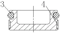
[0022] The present invention includes a cylinder body 1 and an aluminum floating piston 2 arranged inside the cylinder body 1, and the aluminum floating piston 2 moves up and down along the inner wall of the cylinder body 1;

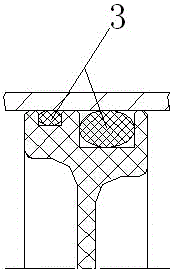
[0023] A sealing ring 3 and a guide piston ring 4 are arranged circumferentially between the cylinder body 1 and the aluminum floating piston 2 .

[0024] The seal ring 3 is arranged on the top of the guide piston ring 4, and the seal ring 3 and the guide piston ring 4 protrude from the aluminum floating piston 2.

[0025] The aluminum floating piston 2 is provided with an empty groove for placing the sealing ring 3 and the guide piston ring 4 .

[0026] The sealing ring 3 and the guide piston ring 4 are arranged symmetrically along the axis of the floating piston 2 .

[0027] The working process of the present invention is that under normal conditions, the seal ring 3 and the guide piston ring 4 are positioned in the hollow groove and slightly protrude...


PUM


Abstract

The invention relates to a ring-type floating piston single-cylinder shock absorber which comprises a cylinder body (1) and an aluminium floating piston (2) arranged in the cylinder body (1), wherein the aluminium floating piston (2) moves up and down along the inner wall of the cylinder body (1); and a sealing ring (3) and a guiding piston ring (4) are circumferentially arranged between the cylinder body (1) and the aluminium floating piston (2). The shock absorber adopts the aluminium floating piston and is provided with the sealing ring and the guiding piston ring, wherein the sealing ring still plays a sealing role, while the guiding piston ring mainly plays a role in guiding the floating piston to slide besides a sealing role, so that the tolerance of the aluminium floating piston can be enlarged appropriately; besides, the aluminium floating piston is still in a stable state under a high-temperature and high-pressure condition, so that adverse effects caused by friction can be reduced greatly, that the floating piston cannot be stuck or cause other adverse effects due to friction during a sliding process is ensured, and the service life and the using effect of the shock absorber are guaranteed.

Description

technical field [0001] The invention relates to a ring-type floating piston single-tube shock absorber, which is mainly used in the technical field of automobiles. Background technique [0002] The shock absorber relies on the floating piston for sealing, and its structural principle is to isolate the shock absorber oil and high-pressure nitrogen in the upper and lower chambers through the floating piston, so the floating piston is required to have good sealing performance, and because the movable piston needs to move up and down in the cylinder , so the floating piston is required to have high strength at the same time; the structural form of the floating piston in the prior art is mainly made of plastic material, and the upper and lower parts of the floating piston are respectively provided with sealing rings that are in contact with the cylinder. The disadvantages of its existence are : [0003] 1) The O-shaped rubber sealing ring on the existing floating piston does not...

Claims


Application Information

Patent Timeline
IPC IPC(8): F16F9/36F16F9/32F16F9/19
CPCF16F9/368F16F9/3214
Inventor 时先荣安学成任宪奇张以峰
Owner YANGZHOU FOCUS SHOCK ABSORBER
Learn More