
Wireless and passive power cable joint temperature monitoring system

A wireless passive and cable joint technology, which is applied to thermometers, signal transmission systems, and parts of thermometers, etc., can solve problems such as non-real-time and active power supply

Inactive Publication Date: 2015-10-28
邢永安
View PDF4 Cites 8 Cited by
  • Summary
  • Abstract
  • Description
  • Claims
  • Application Information

AI Technical Summary

Problems solved by technology

[0003] The present invention proposes a wireless passive power cable joint temperature monitoring system in order to solve the technical problem of not being real-time and requiring active power supply in the traditional temperature measurement method of electric power equipment cable joints

Method used


Image

  • Wireless and passive power cable joint temperature monitoring system

Examples


Embodiment

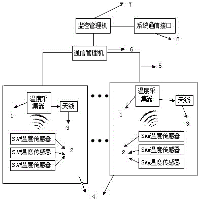
[0015] Embodiment: A wireless passive power cable joint temperature monitoring system based on surface acoustic wave technology, combined with figure 1 The method provided by the present invention is described in detail.

[0016] Specifically, there is a power conversion chip in the temperature collector 1, and its function is to convert the alternating current in the power grid into the 12V direct current required by the temperature collector 1. The SAW temperature sensor 2 obtains energy through the electromagnetic wave signal sent by the temperature collector 1, so the SAW temperature sensor 2 is passive.

[0017] The monitoring and management machine 7 first sets the temperature collection period T according to the specific environment and sends it to the temperature collector 1. The collection period T here can reach 100ms at the fastest, so the scanning frequency of the temperature collector 1 is particularly fast. The temperature collector 1 sends the received temperat...


PUM


Abstract

The present invention relates to a wireless and passive power cable joint temperature monitoring system. The wireless and passive power cable joint temperature monitoring system is characterized in that a temperature collector is communicated with a SAW temperature sensor in a wireless communication manner and is connected with a bus communication management machine, the communication management machine is connected with a monitoring management machine via a bus, and the monitoring management machine is connected with an external monitoring center via a system communication interface. The wireless and passive power cable joint temperature monitoring system can realize the real-time on-line temperature measurement, provides the electric energy with the help of a power grid, is longer in service life, and guarantees the system and device safety and reliability better.

Description

technical field [0001] The invention belongs to the field of temperature measurement of cable joints of electric equipment, and in particular relates to a wireless passive power cable joint temperature monitoring system. Background technique [0002] More than 70% of safety accidents in my country's power system are related to overheating of switch cabinets (cable boxes) and circuit breakers. Switchgear (cable box) failures often lead to power outages and casualties, bringing huge economic losses to enterprises. Contact temperature has long been the primary indicator for warning switchgear (cable box) failures. Therefore, if the temperature of each node can be effectively and automatically monitored online, once an abnormal temperature occurs, an alarm can be uploaded immediately to notify the maintenance personnel to eliminate hidden dangers in time and eliminate the fault in the bud, so as to achieve the purpose of safe power supply. However, in the domestic existing tec...

Claims


Application Information

Patent Timeline
Patent Type & Authority Applications(China)
IPC IPC(8): G01K1/02G08C17/02G01K1/024
Inventor 邢永安
Owner 邢永安
Learn More