LED chip heat dissipation structure

A technology of LED chip and heat dissipation structure, applied in electrical components, circuits, semiconductor devices, etc., can solve problems such as affecting the life of LED light sources, and achieve the effect of heat dissipation

Active Publication Date: 2015-10-28
GOLDEN SCORPION CO LTD
View PDF16 Cites 7 Cited by
  • Summary
  • Abstract
  • Description
  • Claims
  • Application Information

AI Technical Summary

Problems solved by technology

However, as a light source, LED itself has certain defects. One of the problems is heat dissipation, which directly affects the life of the LED light source itself.

Method used


Image

  • LED chip heat dissipation structure
  • LED chip heat dissipation structure

Examples


no. 1 approach

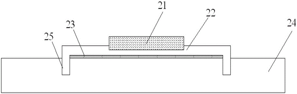
[0017] Such as figure 1 As shown, in the first embodiment of the present invention, a LED chip heat dissipation structure is provided, which includes an LED chip 21, a heat dissipation pad 22 and a heat dissipation substrate 24, a groove is provided on the heat dissipation pad, and the LED chip is arranged in the groove. Part of the side and bottom of the LED chip is in contact with the heat dissipation pad, wherein the heat dissipation pad is provided with at least one heat dissipation pin 25 , and a slot is provided on the heat dissipation substrate, and the heat dissipation pin is inserted into the slot. The form of the groove is not limited, and may be rectangular, square or circular.

[0018] The heat dissipation pad is metal, such as copper, silver or aluminum, and the heat dissipation substrate is a ceramic substrate, such as aluminum oxide or aluminum nitride.

[0019] In the present invention, the heat dissipation pad and the heat dissipation substrate can be combine...

no. 2 approach

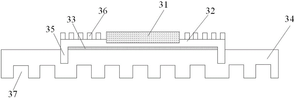
[0026] figure 2 The second embodiment of the present invention is illustrated, the LED chip heat dissipation structure, which includes the LED chip 31, the heat dissipation pad 32 and the heat dissipation substrate 34, the heat dissipation pad is provided with a groove, the LED chip 31 is arranged in the groove, and the LED chip 31 Part of the sides and the bottom are in contact with the heat dissipation pad 32 , wherein the heat dissipation pad is provided with at least one heat dissipation pin 35 , and a slot is provided on the heat dissipation substrate, and the heat dissipation pin 35 is inserted into the slot. The form of the groove is not limited, and may be rectangular, square or circular.

[0027] The heat dissipation pad is metal, such as copper, silver or aluminum, and the heat dissipation substrate is a ceramic substrate, such as aluminum oxide or aluminum nitride.

[0028] In this implementation, a ventilation groove 37 is provided below the heat dissipation subs...


PUM


Abstract

The invention relates to an LED chip heat dissipation structure. The structure includes an LED chip, a heat dissipation cushion and a heat dissipation substrate. The heat dissipation cushion is provided with a groove, and the LED chip is disposed in the groove. Part of the side surface and the bottom of the LED chip are in contact with the heat dissipation cushion. The structure is characterized in that the heat dissipation cushion is at least equipped with a heat dissipation pin, the heat dissipation substrate is equipped with a groove, and the heat dissipation pin is inserted into the groove. Through adoption of the pin and the groove, the heat dissipation cushion and the heat dissipation substrate can be combined together. The pin and the groove achieve fixing and combining effects. Moreover, thermal conduction is achieved when the pin and the groove are in contact, that is to say, heat dissipated from the bottom and the side of the chip is conducted to the heat dissipation substrate through the heat dissipation cushion. Therefore, a heat dissipation function is achieved.

Description

technical field [0001] The invention relates to the field of LEDs, in particular to designing a heat dissipation structure for LED chips. Background technique [0002] Now LED lamps have been widely used in daily life, and have gradually replaced incandescent lamps in the field of lighting. At the same time, LEDs are also actively promoted in other fields. The LED light source has the characteristics of high brightness and energy saving, so it is an environmentally friendly lighting. However, LED as a light source itself has certain defects, one of which is heat dissipation, which directly affects the life of the LED light source itself. Therefore, if the heat dissipation problem can be effectively solved, it has always been the goal of performance pursuit. Contents of the invention [0003] In order to solve the above technical problems, the present invention provides an LED chip heat dissipation structure, which includes an LED chip, a heat dissipation pad and a heat d...

Claims


Application Information

Patent Timeline
Patent Type & Authority Applications(China)
IPC IPC(8): H01L33/64
CPCH01L33/642
Inventor 不公告发明人
Owner GOLDEN SCORPION CO LTD
Why Eureka
Try Eureka