Long-service-life and high-reliability maintainable photovoltaic terminal box

A long-life, junction box technology, used in photovoltaic power generation, photovoltaic modules, electrical components and other directions, can solve the problems of short circuit, fire and explosion accidents, easy stress deformation and sealing of the upper cover, easy deformation and aging of the sealing ring, etc. Volume, improve maintainability, avoid the effect of deformation

Active Publication Date: 2016-04-06
浙江正泰鑫辉光伏有限公司
View PDF8 Cites 7 Cited by
  • Summary
  • Abstract
  • Description
  • Claims
  • Application Information

AI Technical Summary

Problems solved by technology

The disadvantage is that the sealing ring is easy to fall off; the thickness of the upper cover where the sealing ring is located is small and the strength is low; Squeeze the upper cover, the upper cover is prone to stress deformation and cause poor sealing; the sealing ring is not thermally isolated from the inside of the base, and the heat emitted by the components inside the box is easily transferred to the sealing ring, which affects the life of the sealing ring; the sealing ring and the inside of the base are not Electromagnetic isolation, the charging distance between the human body and the charged device inside the box is small, which is easy to cause various short circuits, fires and explosions

Method used


Image

  • Long-service-life and high-reliability maintainable photovoltaic terminal box
  • Long-service-life and high-reliability maintainable photovoltaic terminal box
  • Long-service-life and high-reliability maintainable photovoltaic terminal box

Examples


Embodiment Construction

[0034] The specific embodiments of the present invention will be further described below in conjunction with the accompanying drawings.

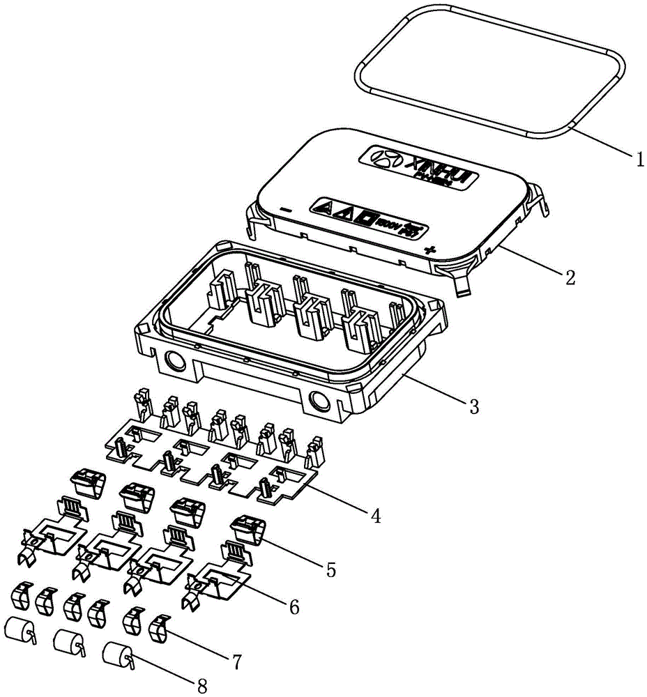
[0035] Such as figure 1 As shown, the photovoltaic junction box of the present invention includes a base 3 and an upper cover 2 that cover each other, a sealing ring 1 is arranged between the base 3 and the upper cover 2, a bottom plate 4 is installed in the base 3, and a plurality of Terminals 6 , each terminal 6 is equipped with a busbar clip 5 and a diode clip 7 , and a diode 8 is installed between the diode clips 7 of adjacent terminals 6 .

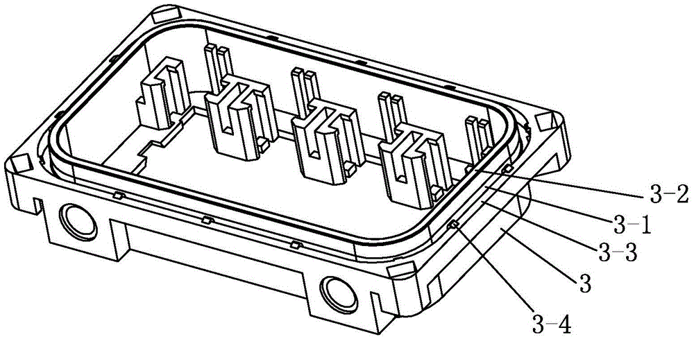
[0036] Such as figure 2 As shown, the top of the base 3 is provided with a circle of annular groove 3-1, and the parts of the base 3 on the inner and outer sides of the annular groove 3-1 constitute the inner wall 3-2 of the annular groove and the outer wall 3 of the annular groove respectively. -3. The height of the inner wall 3-2 of the annular groove is greater than the height of the outer wa...


PUM


Abstract

The invention discloses a long-service life and high-reliability maintainable photovoltaic terminal box. The terminal box comprises a base, an upper cover, a sealing ring, a bottom plate, terminals, a confluence band clamp, a diode clamp and a dido; the sealing ring is arranged in an annular groove in the base and blocked by a buckling hook on the outer wall of the annular groove; when the upper cover is matched with the base, the cover edge is inserted in the annular groove to extrude the sealing ring to form sealing; a special-shaped sealing ring is arranged in a sealing ring placement groove in a wiring port of the base; and two sealing interference regions on the special-shaped sealing ring are in interference with a cable and the inner wall of the sealing ring placement groove respectively, so that the reliable sealing for the photovoltaic terminal box is realized. The confluence band clamp and the diode clamp both adopt a cage-type structure; and meanwhile, after the confluence band clamp and the diode clamp are assembled on the terminals, the overall structure of the assembled confluence band clamp and the diode clamp is positioned on the outer sides of the terminals, so that the radiating area is enlarged, concentrated heating is avoided, and the reliable radiation and the maintainability of the photovoltaic terminal box are realized.

Description

technical field [0001] The invention relates to the field of structural design of a photovoltaic junction box, in particular to a long-life, highly reliable and maintainable photovoltaic junction box. Background technique [0002] The photovoltaic junction box is an important part used to connect photovoltaic modules and inverters in solar power generation systems. [0003] The application occasions of photovoltaic junction boxes include various harsh environments. It is one of the goals of photovoltaic junction box design to make the photovoltaic junction box well sealed and prevent external media from penetrating into the junction box and affecting the internal functions. Existing photovoltaic junction boxes are mostly sealed by potting glue for cable inlets, which have high requirements for technology. If the technology is not up to standard, air bubbles are likely to occur and cause sealing failure, thereby affecting the reliability of the photovoltaic junction box and r...

Claims


Application Information

Patent Timeline
Patent Type & Authority Applications(China)
IPC IPC(8): H02S40/34
CPCY02E10/50
Inventor 彭祁军
Owner 浙江正泰鑫辉光伏有限公司
Why Eureka
Try Eureka