Pattern-reconfigurable antenna based on graphene composite structure frequency selective surface

A frequency-selective surface and graphene composite technology, applied in antennas, electrical components, etc., can solve the problem of inability to flexibly change the antenna gain and beam width, and achieve the effect of changing the beam width and increasing the gain

Active Publication Date: 2015-10-28
XIDIAN UNIV
View PDF0 Cites 44 Cited by
  • Summary
  • Abstract
  • Description
  • Claims
  • Application Information

AI Technical Summary

Problems solved by technology

[0018] The purpose of the present invention is to overcome the deficiencies in the above-mentioned prior art, and propose a reconfigurable antenna with a pattern based on a graphene composite structure frequency selective surface, which is used to solve the problem that the reconfigurable antenna with a pattern cannot flexibly change the antenna The problem of gain and beam width can meet the needs of modern communication systems for flexible and changeable millimeter-wave antenna patterns

Method used


Image

  • Pattern-reconfigurable antenna based on graphene composite structure frequency selective surface
  • Pattern-reconfigurable antenna based on graphene composite structure frequency selective surface
  • Pattern-reconfigurable antenna based on graphene composite structure frequency selective surface

Examples


Embodiment 1

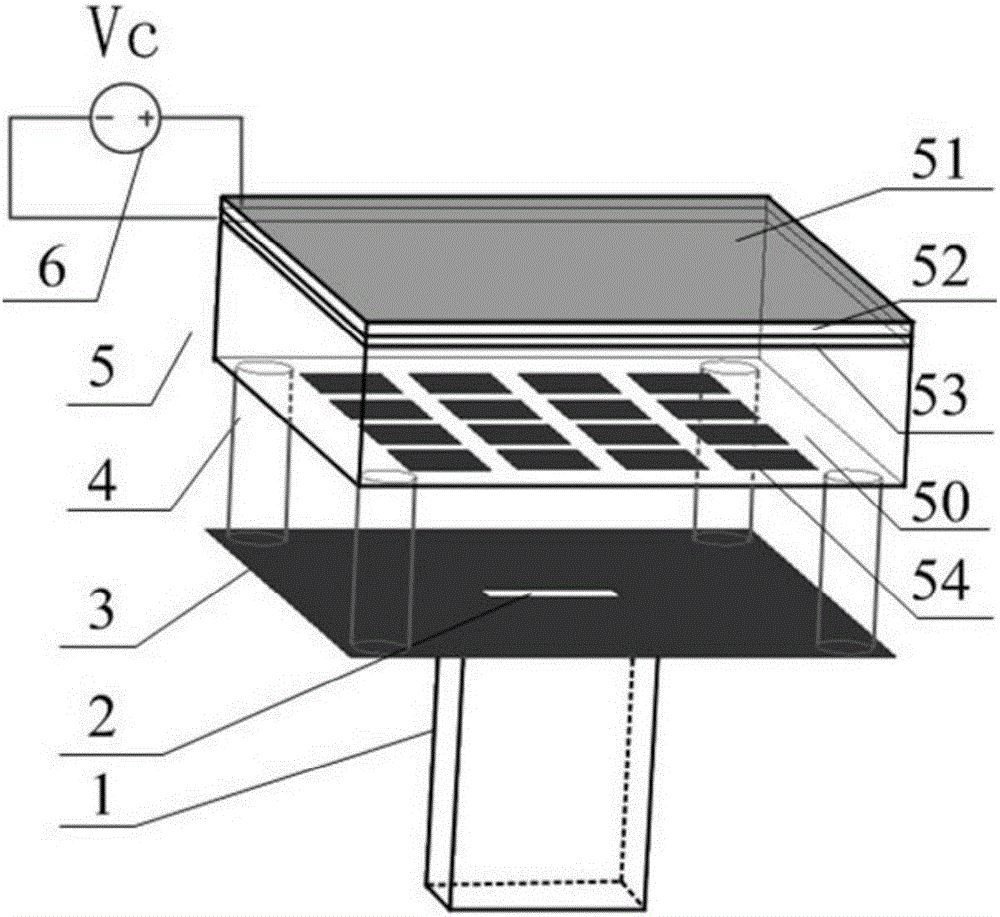
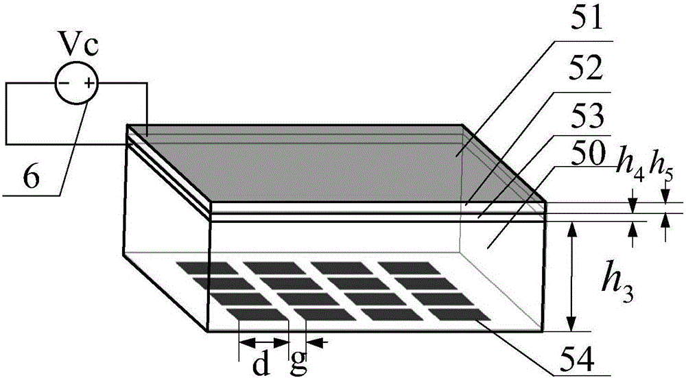
[0040] refer to figure 1 , the present invention includes a rectangular waveguide feeder 1, a rectangular radiation unit 2, a reflector 3, four support columns 4, a frequency selective surface 5 and a DC bias Vc 6, wherein the frequency selective surface 5 includes a dielectric substrate 50, pasted on the dielectric substrate The graphene composite structure on the surface and the square patch array 54 printed on the lower surface of the dielectric substrate, the graphene composite structure consists of a graphene layer 51, an aluminum oxide layer 52 and a polysilicon layer 53 stacked sequentially from top to bottom. A DC bias voltage Vc6 is added between the alkene layer 51 and the polysilicon layer 53 to regulate the surface conductivity of graphene; the aluminum oxide layer 52 in the graphene composite structure is used to isolate the polysilicon layer 53 and the graphene layer 51 to form a Bias voltage; the frequency selective surface 5 is fixed above the reflector 3 throu...

Embodiment 2

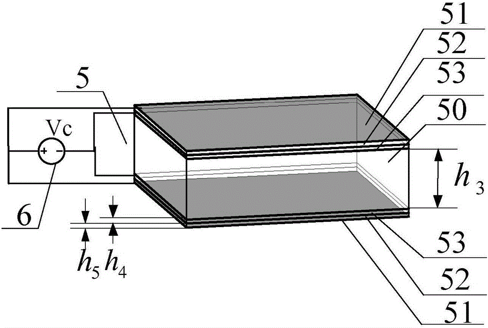
[0050] Embodiment 2 except the structure of the frequency selective surface, other structures are the same as embodiment 1, and the structural diagram of the frequency selective surface adopted in embodiment 2 is as follows image 3 as shown,

[0051] refer to image 3 , the frequency selective surface in this embodiment is only to replace the square patch array 54 originally printed on the lower surface of the dielectric substrate with a graphene composite structure, next to the dielectric substrate is a polysilicon layer 53, followed by an aluminum oxide layer 52 and graphene layer 51; the width of this composite structure is identical with reflective plate 3 widths, and the thickness of dielectric substrate is identical with embodiment 1 h 3 =4.5mm, the thickness is determined by the working wavelength λ in the medium g decision, the approximate formula is h 3 =λ g / 2; supporting column 4, reflector 3, rectangular radiation unit 2, and rectangular waveguide feeder 1 are...


PUM


Abstract

The invention provides a pattern-reconfigurable antenna based on a graphene composite structure frequency selective surface to solve the problem that the gain and beam bandwidth of an antenna cannot be changed flexibly in the prior art. The pattern-reconfigurable antenna comprises a rectangular waveguide feeder, a rectangular radiation element, a baffle board, a frequency selective surface, and a direct-current bias voltage Vc. The frequency selective surface includes a graphene composite structure, a dielectric substrate, and a square patch array or graphene composite structure, which are stacked from top to bottom. The graphene composite structure is composed of a graphene layer, an alumina layer and a polycrystalline silicon layer which are stacked sequentially. The direct-current bias voltage Vc is applied between the graphene layer and the polycrystalline silicon layer. The rectangular radiation element is arranged on the baffle board, the frequency selective surface is fixed above the baffle board through four support columns, and the rectangular waveguide feeder is fixed below the baffle board. The radiation gain and beam bandwidth of the antenna can be changed flexibly, and reconfigurable pattern of a millimeter wave antenna is realized.

Description

technical field [0001] The invention belongs to the technical field of antennas, and relates to a reconfigurable antenna for adjusting a radiation pattern through a composite frequency-selective surface loaded with graphene, which can be used for signal transmission and reception of a radio frequency terminal of a millimeter wave communication system. Background technique [0002] As a component used to transmit or receive radio waves, the antenna is an indispensable part of the wireless communication system. With the rapid development of wireless communication, the requirements for antennas are getting higher and higher. On the one hand, it is necessary to enable the antenna to work in multiple frequency bands, have multiple working modes and have good transmission performance. On the other hand, it is necessary to reduce the weight of the antenna, reduce the volume of the antenna and reduce the cost. It is precisely because of this demand that the concept of reconfigurab...

Claims


Application Information

Patent Timeline
Patent Type & Authority Applications(China)
IPC IPC(8): H01Q3/44
Inventor 吴边张振龙赵雨桐赵勋旺林磊
Owner XIDIAN UNIV
Why Eureka
Try Eureka