An Analog Beamforming Method with Arbitrary Beamwidth

A technology for simulating beams and widths, applied in diversity/multi-antenna systems, transmission monitoring, space transmit diversity, etc., can solve problems such as increasing energy and loss of degrees of freedom, achieve complexity optimization, and overcome constant modulus constraints

Active Publication Date: 2020-08-18
BEIHANG UNIV
View PDF4 Cites 0 Cited by
  • Summary
  • Abstract
  • Description
  • Claims
  • Application Information

AI Technical Summary

Problems solved by technology

The cost of this method is to use multiple RF chains, which greatly increases the loss of energy and degrees of freedom

Method used


Image

  • An Analog Beamforming Method with Arbitrary Beamwidth
  • An Analog Beamforming Method with Arbitrary Beamwidth
  • An Analog Beamforming Method with Arbitrary Beamwidth

Examples


Embodiment Construction

[0021] The technical solutions of the present invention will be described below in conjunction with the drawings and embodiments.

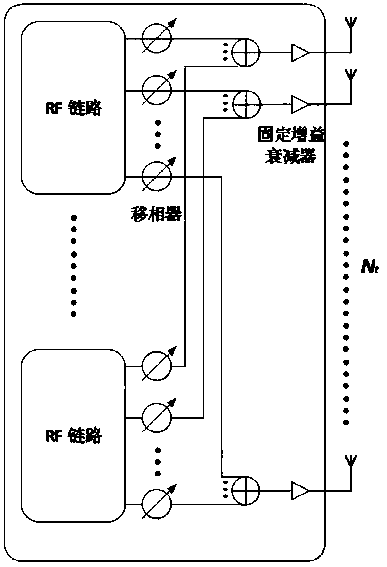
[0022] The invention provides an analog beam forming method with arbitrary width, and also provides a new analog beam forming hardware structure.

[0023] Consider a discrete sequence n=0,1,...,N t -1, A, a, b, c are all real numbers; where N t is the number of antennas, A is the constant amplitude of the sequence, and c is the initial phase. Since the values ​​of A and c do not affect the beamforming effect, this embodiment of the present invention assumes that A=1 and c=0. Then the general form of the expression of the discrete sequence is

[0024]

[0025] Since if it is expressed in another way, the above formula can be split into the form of multiplying two sequences, as follows

[0026] w[n]=p[n]q[n]

[0027] in,

[0028] p[n]=e jπmn ;n=0,1,...,N t -1 (2)

[0029]

[0030] where N t is the number of transmitting antennas, m...


PUM


Abstract

The invention discloses a random wave beam width simulation wave beam forming method and belongs to the wireless communication technology field. A fixed gain attenuator is employed on a hardware structure for realization, and each array element is connected with a fixed gain attenuator to form a window function sequence. According to the method, firstly, wave beam generation width and a center angle are determined, secondly, a linear frequency modulation sequence is taken as a weight vector, and the wave beam width and the center angle are adjusted through changing a parameter of the sequence; problems of wide wave beam, large main lobe fluctuation and slow transition zone decrease are solved through employing a spatial domain windowing scheme. The method is advantaged in that not only can constant modulus constraints formed by wave beam simulation be solved, but also waveform is optimized on the condition that the high complex degree does not increase.

Description

technical field [0001] The invention relates to an analog beam forming method with arbitrary beam width, belonging to the technical field of wireless communication. Background technique [0002] In the 5G system, millimeter wave (mmWave) and massive antenna array (massive MIMO) are two key technologies. The Massive MIMO system can increase the array gain and diversity gain through a larger antenna array, and the system throughput is greatly increased. Massive MIMO can align users by forming very narrow beams, thereby improving the user's receiving signal-to-noise ratio and reducing interference to adjacent users. In the millimeter wave system, due to the limitation of radio frequency (RF) link power consumption and hardware complexity, the massive MIMO system cannot guarantee that each antenna is connected to an RF link, so the digital beamforming method in the traditional MIMO system No longer applicable. Instead, the analog beamforming implemented by the phase shifter g...

Claims


Application Information

Patent Timeline
Patent Type & Authority Patents(China)
IPC IPC(8): H04B7/06H04B7/0456H04B17/391
CPCH04B7/0465H04B7/0617H04B17/3912
Inventor 田亚飞彭睿
Owner BEIHANG UNIV
Why Eureka
Try Eureka