Method and system for ensuring automatic powering-off of intelligent mobile terminal after full charging

An intelligent mobile terminal, automatic power-off technology, applied in battery circuit devices, current collectors, electric vehicles, etc., can solve problems such as high cost, power-off protection, and difficulty in product promotion and application, and achieve simple use, simplified connection and The effect of the distribution process

Inactive Publication Date: 2015-10-28
上海汉枫电子科技有限公司
View PDF2 Cites 5 Cited by
  • Summary
  • Abstract
  • Description
  • Claims
  • Application Information

AI Technical Summary

Problems solved by technology

However, most of these chargers are very expensive, and there is no actual visible effect to prov

Method used


Image

  • Method and system for ensuring automatic powering-off of intelligent mobile terminal after full charging
  • Method and system for ensuring automatic powering-off of intelligent mobile terminal after full charging
  • Method and system for ensuring automatic powering-off of intelligent mobile terminal after full charging

Examples


Embodiment 1

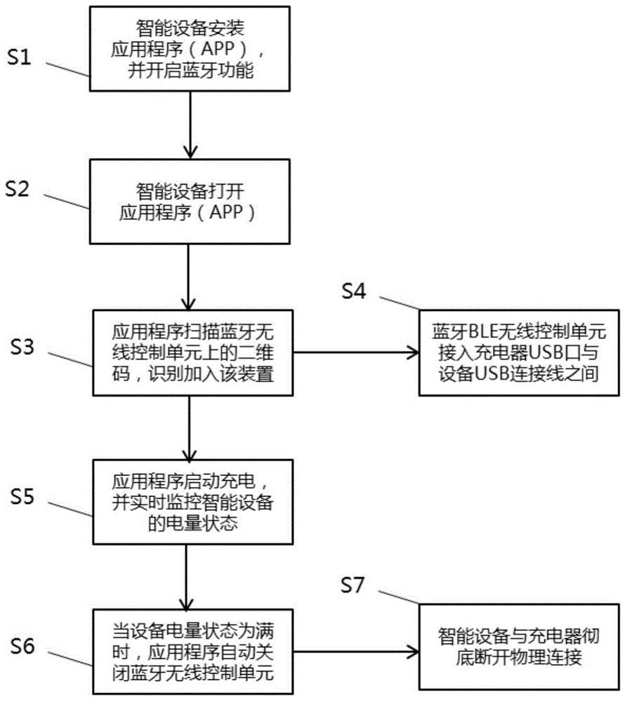
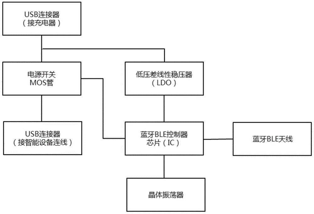
[0035] Such as figure 1 and figure 2 As shown, the present invention guarantees a system for automatically powering off a smart mobile terminal after being fully charged, which includes a USB connector for connecting a charger and an APP installed in a smart mobile terminal; the charger is connected to the smart mobile terminal A Bluetooth BLE wireless control unit is arranged between the mobile terminals; the Bluetooth BLE wireless control unit includes a Bluetooth BLE controller chip; the USB connector is connected to a power switch MOS tube and a low-dropout linear regulator through a +5V power supply line; The low dropout linear voltage regulator is used to provide +3.3V voltage to the Bluetooth BLE controller chip; the output end of the power switch MOS tube is connected to the USB connector, and the Bluetooth BLE controller chip is connected to the crystal oscillator device and Bluetooth BLE antenna connection.

[0036] A method for ensuring that an intelligent mobile...

Embodiment 2

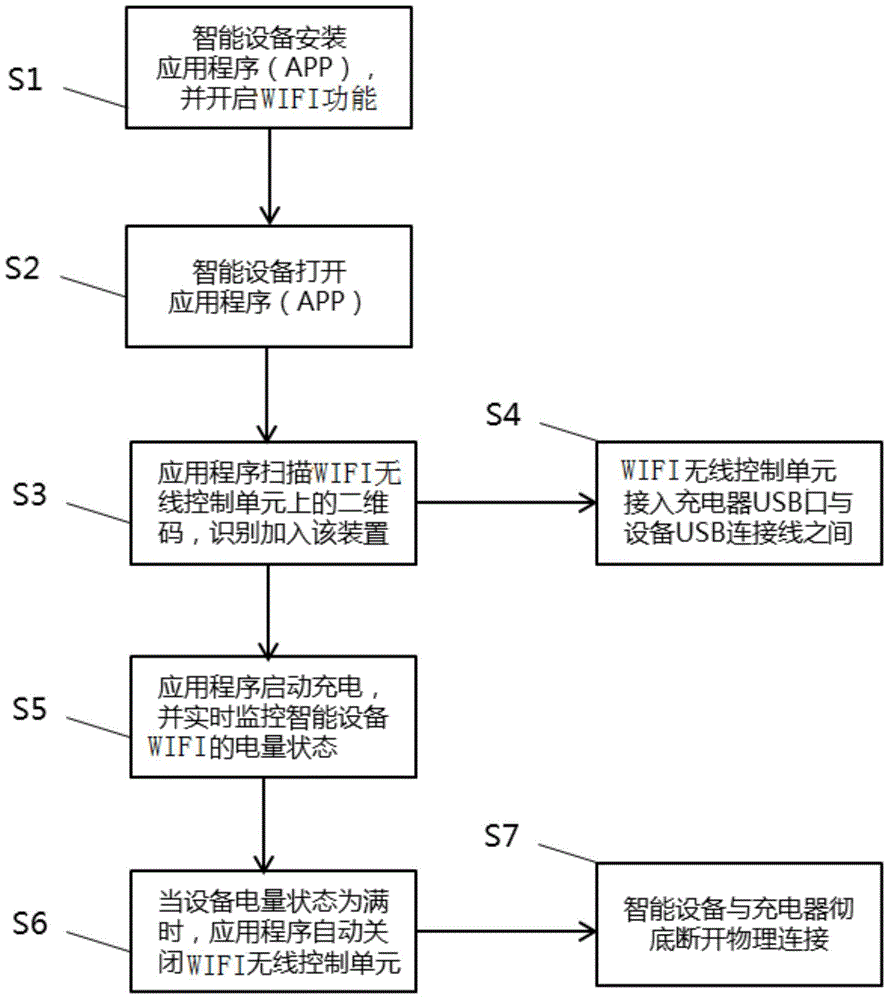
[0045] Such as image 3 and Figure 4 As shown, the present invention guarantees a system for automatically powering off a smart mobile terminal after being fully charged, which includes a USB connector for connecting a charger and an APP installed in a smart mobile terminal; the charger is connected to the smart mobile terminal A WIFI wireless control unit is arranged between the mobile terminals; the WIFI wireless control unit includes a WIFI controller chip; the USB connector is connected to a power switch MOS tube and a low-dropout linear regulator through a +5V power supply line; the low-voltage The differential linear voltage regulator is used to provide +3.3V voltage to the WIFI controller chip; the output end of the power switch MOS tube is connected to the USB connector, and the WIFI controller chip is connected to the crystal oscillator and the WIFI antenna .

[0046] A method for ensuring that an intelligent mobile terminal is automatically powered off after being...


PUM


Abstract

The invention discloses a system for ensuring automatic powering-off of an intelligent mobile terminal after full charging. The system comprises a USB connector used to connect a charger, and an APP mounted in an intelligent mobile terminal. A wireless control unit is arranged between the charger and the intelligent mobile terminal, and the wireless control unit includes a controller chip. The USB connector is connected with a power switch MOS tube and a low-dropout linear regulator through a +5V power supply line. The low-dropout linear regulator is used to provide +3.3V voltage for the controller chip. The output end of the power switch MOS tube is connected with the USB connector. The controller chip is connected with a crystal oscillator. The invention further provides a method for ensuring automatic powering-off of an intelligent mobile terminal after full charging. The charging state of the intelligent mobile terminal is read through the APP of the intelligent mobile terminal, which is simple, intuitive and accurate. The problem that inaccurate and false judgment is caused by factors such as device aging for a traditional detection circuit for judging 'full charge' is completely solved.

Description

technical field [0001] The invention relates to a method and system for ensuring that an intelligent mobile terminal is automatically powered off after being fully charged. Background technique [0002] At present, smart terminal devices such as mobile phones and PADs consume a lot of power. People are used to charging at night, but mobile phones will cause overcharging overnight, which will greatly damage the battery life of smart terminal devices. Moreover, due to the uneven quality of chargers, some chargers do not have a charging protection circuit at all, and cannot play a basic role in protecting the device being charged. safety incidents. [0003] At present, there are smart chargers with overcharge protection function known as "full power cut off" on the market, which use a series of algorithms to detect whether the connected device is "full charge", and then prevent the flow of current, and finally realize as The smart mobile terminal is fully charged, and the bat...

Claims


Application Information

Patent Timeline
IPC IPC(8): H02J7/02
Inventor 邱海一
Owner 上海汉枫电子科技有限公司
Why Eureka
Try Eureka