Flow-spoiling type electronic-cigarette smoke tube structure
A disruptive, electronic cigarette technology, applied in the direction of tobacco, smoker's products, applications, etc., can solve the problems of high temperature of electronic cigarette, hot mouth, and unpleasant smokers.
- Summary
- Abstract
- Description
- Claims
- Application Information
AI Technical Summary
Problems solved by technology
Method used
Image
Examples
Embodiment 1
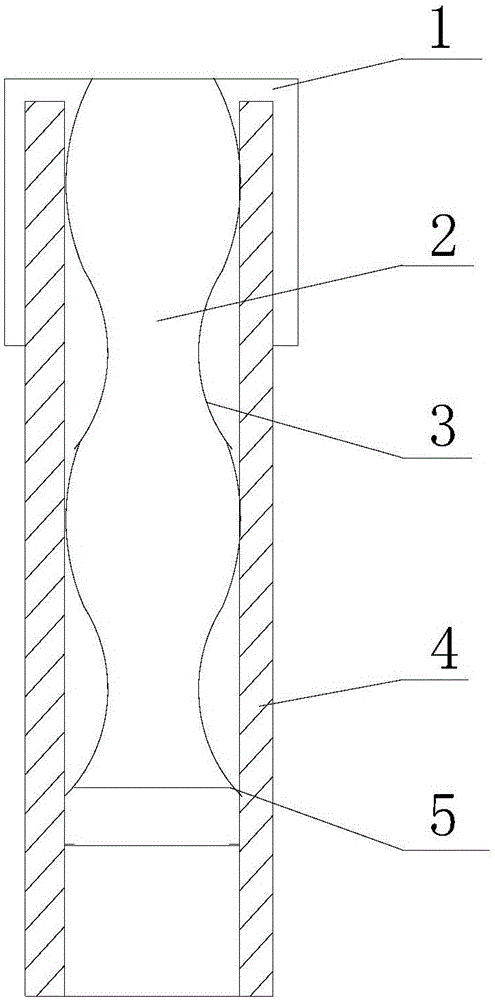
[0027] like figure 1 As shown, it is the structure of the spoiler-type electronic cigarette airway of the present invention. The airway includes a smoking pipe 4, which generally refers to the combination of the atomization smoke pipe, the flue connecting pipe and the mouthpiece on the upper side of the electronic cigarette atomizer. A smoking air passage 2 for smoke is formed inside the assembly, and the inside of the smoking air passage 2 is generally in the shape of a circular tube. A bellows 3 is arranged inside the circular tube, and the bellows 3 has an arc protruding into the smoking air passage 2. The existence of the arc makes the smoking air passage 2 have different ventilation cross-sectional areas at different positions. The part with a small area plays a certain role in disturbing the airflow, so that the airflow speed can be accelerated, and then the airflow speed can be changed. The speed of the airflow can change from time to time according to the cross-section...
Embodiment 2
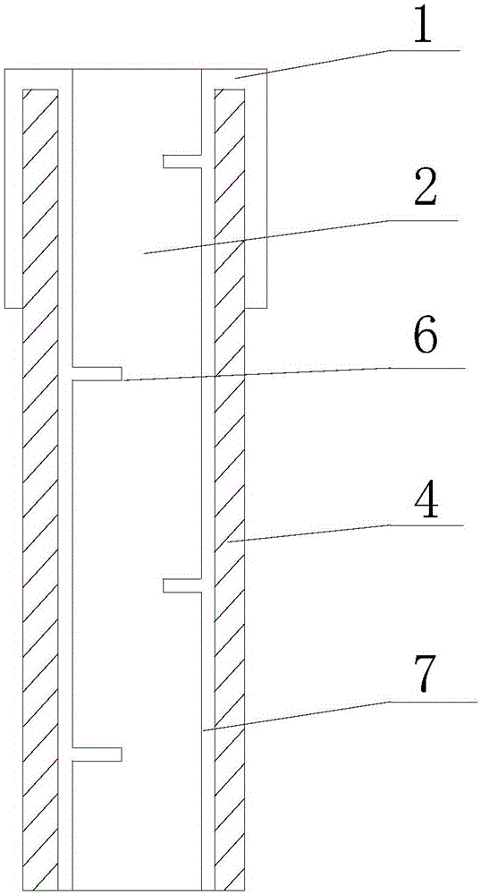
[0031] like figure 2 As shown, the structure of the flow-disrupting electronic cigarette air passage in this embodiment is that a flow-disturbing blade 6 is arranged in the smoking air passage 2 in the smoking pipe 4, and the flow-disturbing blade 6 is fixedly arranged on a connecting sleeve 7 Inside. The turbulent blades 6 are arcuate in shape, and are fixedly arranged on the inner wall of the connecting sleeve 7, and there are a plurality of these turbulent blades 6, and two adjacent blades are respectively arranged on the left and right sides, and are staggered from each other in the axial direction . like figure 2 Shown are staggered spacing settings. This structure can make the gas mist meet the spoiler blade 6 and change direction in the process of upward flow, so as to produce different effects.
[0032] like figure 2 As shown, the connecting sleeve 7 is set in the smoking pipe 4, and the upper end is provided with a fixing ring 1. After the fixing ring 1 is fix...
Embodiment 3
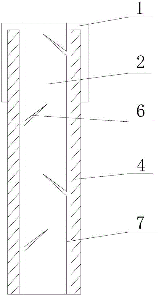
[0033] Embodiment 3: as image 3 As shown, the difference between this embodiment and Embodiment 2 is that the turbulent vanes 6 and the inner wall of the smoking duct 4 are arranged in an inclined direction, which is upwardly inclined, and of course may also be downwardly inclined.
[0034] The structure of this embodiment is to change the flow direction of the airflow by using the spoiler blades 6 to disturb the flow rate of the airflow, and force the airflow to change direction, thereby realizing the change of the airflow state, preventing mouth scalding, and preventing liquid droplets from being sucked into the oral cavity.
PUM
 Abstract
Description
Claims
Application Information
 - R&D
- Intellectual Property
- Life Sciences
- Materials
- Tech Scout
- Unparalleled Data Quality
- Higher Quality Content
- 60% Fewer Hallucinations
Browse by: Latest US Patents, China's latest patents, Technical Efficacy Thesaurus, Application Domain, Technology Topic, Popular Technical Reports.
© 2025 PatSnap. All rights reserved.Legal|Privacy policy|Modern Slavery Act Transparency Statement|Sitemap|About US| Contact US: help@patsnap.com


