
closed chest drain

A drainage device and closed-type technology, applied in the field of chest cavity closed drainage device, can solve the problems of inconvenient use and complex structure of the drainage device, and achieve the effects of facilitating maintenance and protection, preventing accidental fall, and improving air tightness

Active Publication Date: 2017-12-29
江西罡龙医疗器械有限公司
View PDF7 Cites 1 Cited by
  • Summary
  • Abstract
  • Description
  • Claims
  • Application Information

AI Technical Summary

Problems solved by technology

[0003] In order to overcome the disadvantages of inconvenient use and complex structure of the drainage device in the prior art, a closed chest drainage device is provided

Method used


Image

  • closed chest drain
  • closed chest drain
  • closed chest drain

Examples


Embodiment 1

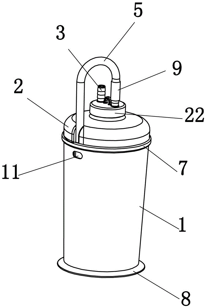
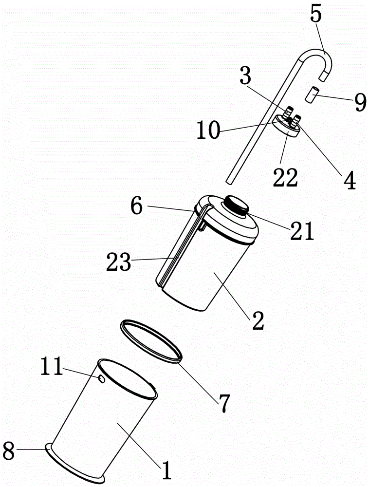
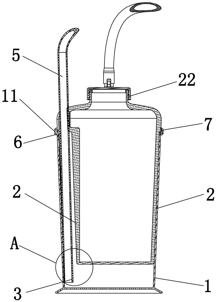
[0030] Such as Figure 1-5 As shown, a closed thoracic drainage device includes a saline bucket 1 and a drainage bottle 2, the drainage bottle 2 is a hollow closed cavity, the saline bucket 1 is an open mouth, and the top of the drainage bottle 2 is set There is a drainage tube interface 3 and a water seal tube interface 4, the drainage bottle 2 is plugged into the brine bucket 1, and a hollow cavity structure of brine is formed between the bottom of the drainage bottle 2 and the bottom of the cavity of the brine bucket 1 The water-sealed tube 5 connects the drainage bottle 2 with the inner cavity of the saline chamber through the water-sealed tube interface 4, and the free end of the water-sealed tube 5 extends below the physiological saline level in the saline chamber. Since there is a gap between the slots of the water-sealed tube and the water-sealed tank, there will be air circulation in this gap. The drainage bottle of the closed chest drainage device of the present in...

Embodiment 2

[0043] Parts in this embodiment that are the same as those in Embodiment 1 will not be repeated, and the differences are as follows.

[0044] Such as Figure 6 As shown, the drainage bottle 2 in this embodiment does not have a water-sealed tube slot, but a number of vertical convex grooves 12 are provided on the side wall of the brine bucket 1, and the water-sealed tube 5 passes through The convex groove 12 extends into the brine chamber, and the cross section of the convex groove 12 is greater than or equal to the cross section of the water seal pipe 5, and several exhaust inlets corresponding to the convex groove 12 are provided on the side wall of the brine bucket 1. The liquid port 11 and the convex groove 12 run through the upper and lower surfaces of the drainage bottle 2 .

[0045] Several vertical convex grooves 12 are arranged on the side wall of the brine bucket 1, the water seal pipe 5 extends into the brine chamber through the convex grooves 12, and the cross sec...


PUM


Abstract

The invention discloses a chest cavity closed drainage device, which comprises a saline bucket and a drainage bottle, the drainage bottle is a hollow airtight cavity, the saline bucket is an open mouth, and the top of the drainage bottle is provided with a drainage tube interface and the water seal tube interface, the drainage bottle is plugged into the brine bucket, and a brine chamber with a hollow cavity structure is formed between the bottom of the drainage bottle and the cavity bottom of the brine bucket, and the water seal tube passes through the water seal tube interface The drainage bottle is communicated with the inner cavity of the saline chamber and the free end of the water-sealed tube extends below the level of the physiological saline in the saline chamber. The drainage bottle of the closed chest drainage device of the present invention is inserted into the saline bucket to form an integral structure, which avoids the inconvenience caused by two separate bottles in the traditional drainage device.

Description

technical field [0001] The invention relates to a medical device, in particular to a closed chest drainage device. Background technique [0002] In the medical field, when there is air and fluid accumulation in the patient's pleural cavity, it may lead to lung collapse, decreased respiratory function, and even life-threatening, and closed thoracic drainage is usually performed for such patients. The most widely used drainage device in the existing clinical medicine is the closed chest drainage bottle, which is composed of two bottles side by side, including a drainage chamber, a saline chamber, a catheter, a water-sealed tube and an outlet tube, and the catheter is connected to the chest tube. The effusion and air in the patient's pleural cavity enter the drainage cavity through the chest tube and the catheter tube, the effusion is stored in the drainage cavity, and the overflowing air enters the saline bottle from the water-sealed tube and is discharged from the trachea. A...

Claims


Application Information

Patent Timeline
Patent Type & Authority Patents(China)
IPC IPC(8): A61M1/00
CPCA61M1/0001A61M2202/0492A61M1/61
Inventor 周勇飞
Owner 江西罡龙医疗器械有限公司
Learn More