
Positive end-expiratory pressure control system and method

A positive end-expiratory pressure, control system technology, applied in the field of medical electronics, can solve the problems of weak pressure relief, complex mechanical structure, cumbersome operation, etc., to achieve the effect of high stability and high safety factor

Active Publication Date: 2015-11-04
AMBULANC (SHENZHEN) TECH CO LTD
View PDF6 Cites 8 Cited by
  • Summary
  • Abstract
  • Description
  • Claims
  • Application Information

AI Technical Summary

Problems solved by technology

Mechanical positive end-expiratory pressure control mode PEEP valve has a built-in adjustment spring, the mechanical structure is complex and bulky, the elastic accuracy of the spring is poor, the PEEP pressure cannot be accurately controlled and the PEEP pressure cannot be continuously adjusted, the safety factor is insufficient, and the air consumption is large , the mechanical PEEP valve needs to be manually adjusted, and the operation is cumbersome
The excitation motor or excitation coil control method uses the excitation motor for control. The excitation motor is large in size, which makes the mechanical structure design of the product complex. Secondly, the excitation motor has a slow response speed and cannot quickly respond to PEEP pressure changes. The safety factor is low and the price is expensive.
The existing pneumatic PEEP control method has relatively weak pressure relief capability, slow pressure relief speed, and slow PEEP pressure response speed

Method used


Image

  • Positive end-expiratory pressure control system and method
  • Positive end-expiratory pressure control system and method
  • Positive end-expiratory pressure control system and method

Examples


Embodiment Construction

[0031] In order to make the technical problems solved by the present invention, the technical solutions adopted and the technical effects achieved clearer, the technical solutions of the present invention will be further described in detail below in conjunction with the accompanying drawings. Obviously, the described embodiments are only part of the implementation of the present invention. example, not all examples. Based on the embodiments of the present invention, all other embodiments obtained by those skilled in the art without making creative efforts belong to the protection scope of the present invention.

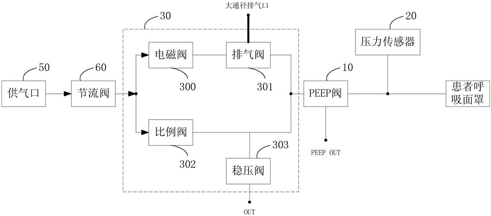
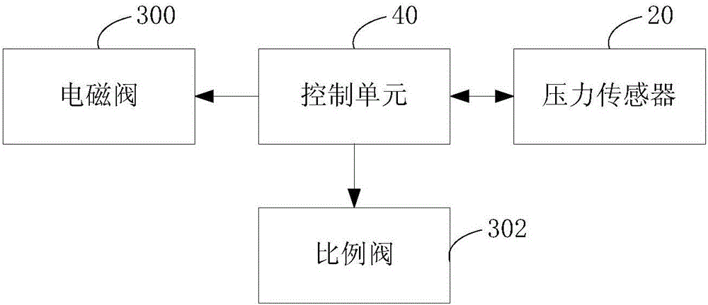
[0032] figure 1 It is a structural schematic diagram of the positive end-expiratory pressure control system provided by the present invention. figure 2 It is a block diagram of the positive end-expiratory pressure control circuit provided by the present invention. refer to figure 1 , figure 2 As shown, the positive end-expiratory pressure control system includes...


PUM


Abstract

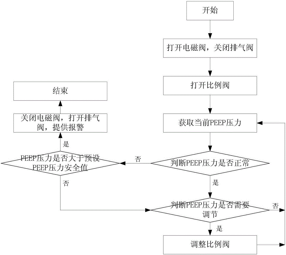
The invention discloses a positive end-expiratory pressure control system, and the system comprises a PEEP valve which is connected with a patient breathing tube; and a pressure sensor, a bypass of which is connected to connection ends of the PEEP valve and the patient breathing tube. The PEEP pneumatic control assembly comprises a solenoid valve, a vent valve, a proportional valve, and a pressure stabilizing valve, wherein one end of the solenoid valve is connected with an air supply port air circuit, and the other end of the solenoid valve is connected with a vent valve air circuit. The other end of the vent valve is connected with a PEEP valve air circuit, and the vent valve is provided with a large drift diameter exhaust port which is communicated with the atmosphere. One end of the proportional valve is connected with the air supply port air circuit, and the other end of the proportional valve is connected with the PEEP valve and the vent valve air circuit. One end of the pressure stabilizing valve is connected to an air circuit between the proportional valve and the PEEP valve, and the other end of the pressure stabilizing valve is connected with the atmosphere. The system also comprises a control unit which adjusts the PEEP pressure to be different values. The system can achieve quick venting and decompression through the large drift diameter exhaust port, is high in safety factor, enables PEEP pressure control to be accurate, is quick in response, and is high in stability.

Description

technical field [0001] The invention relates to the technical field of medical electronics, in particular to a positive end-expiratory pressure control system and method. Background technique [0002] PEEP is the positive end-expiratory pressure. When the airway is opened at the end of expiration, the airway pressure remains higher than atmospheric pressure to prevent alveolar atrophy and collapse, and can expand the atrophied and collapsed alveoli and recruit atelectatic alveoli, thereby increasing Functional residual capacity and compliance of the lungs, which facilitate oxygen diffusion. When the PEEP increases abnormally, the patient's work of exhalation increases, causing difficulty in exhaling, which may cause the risk of suffocation. With the development of medical technology, higher requirements are put forward for the control accuracy, response speed and safety performance of PEEP. [0003] At present, there are mainly three PEEP control methods used by ventilator...

Claims


Application Information

Patent Timeline
IPC IPC(8): A61M16/00A61M16/20
Inventor 冯耿超黄志昂韩永光
Owner AMBULANC (SHENZHEN) TECH CO LTD
Learn More