Groove wheel turnover device with auxiliary positioning function

A flipping device and auxiliary positioning technology, which is applied in the direction of feeding device, grinding device, grinding drive device, etc., can solve the problems of insufficient positioning accuracy and affect positioning reliability, and achieve the effect of reliable positioning

Active Publication Date: 2015-11-04
GUANGZHOU UNIVERSITY
View PDF6 Cites 18 Cited by
  • Summary
  • Abstract
  • Description
  • Claims
  • Application Information

AI Technical Summary

Problems solved by technology

However, due to the influence of processing and assembly precision, there must be a certain gap between the concave and convex locking arcs of the above-mentioned sheave turning mechanism. The disadvantage of insufficient precision seriously affects the reliability of positioning

Method used


Image

  • Groove wheel turnover device with auxiliary positioning function
  • Groove wheel turnover device with auxiliary positioning function
  • Groove wheel turnover device with auxiliary positioning function

Examples


example 1

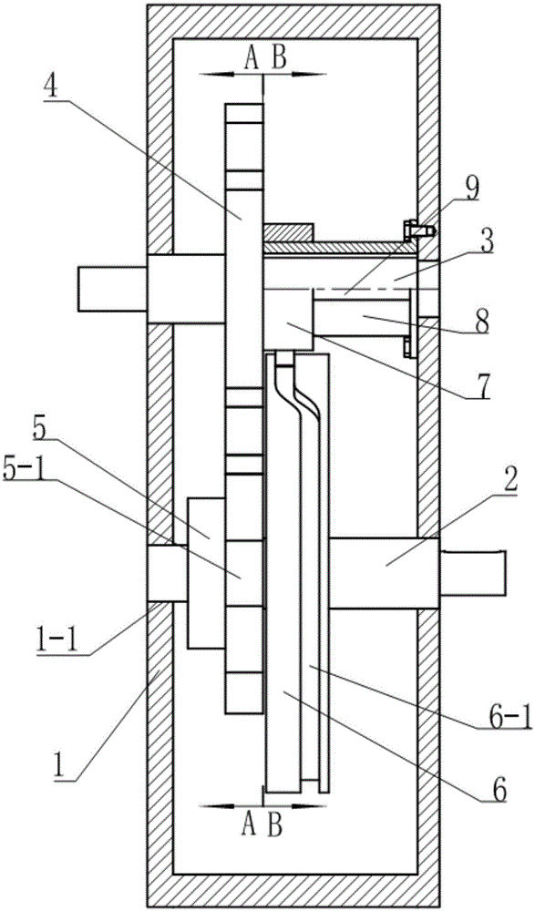
[0026] See Figure 1~4 , The sheave turning device in this example includes a box body 1, a transmission mechanism that drives the workpiece to turn, and an auxiliary positioning mechanism;

[0027] The box body 1 is provided with a support seat 1-1 for supporting the first transmission shaft 2 and the second transmission shaft 3, and the axes of the first transmission shaft 2 and the second transmission shaft 3 are parallel;

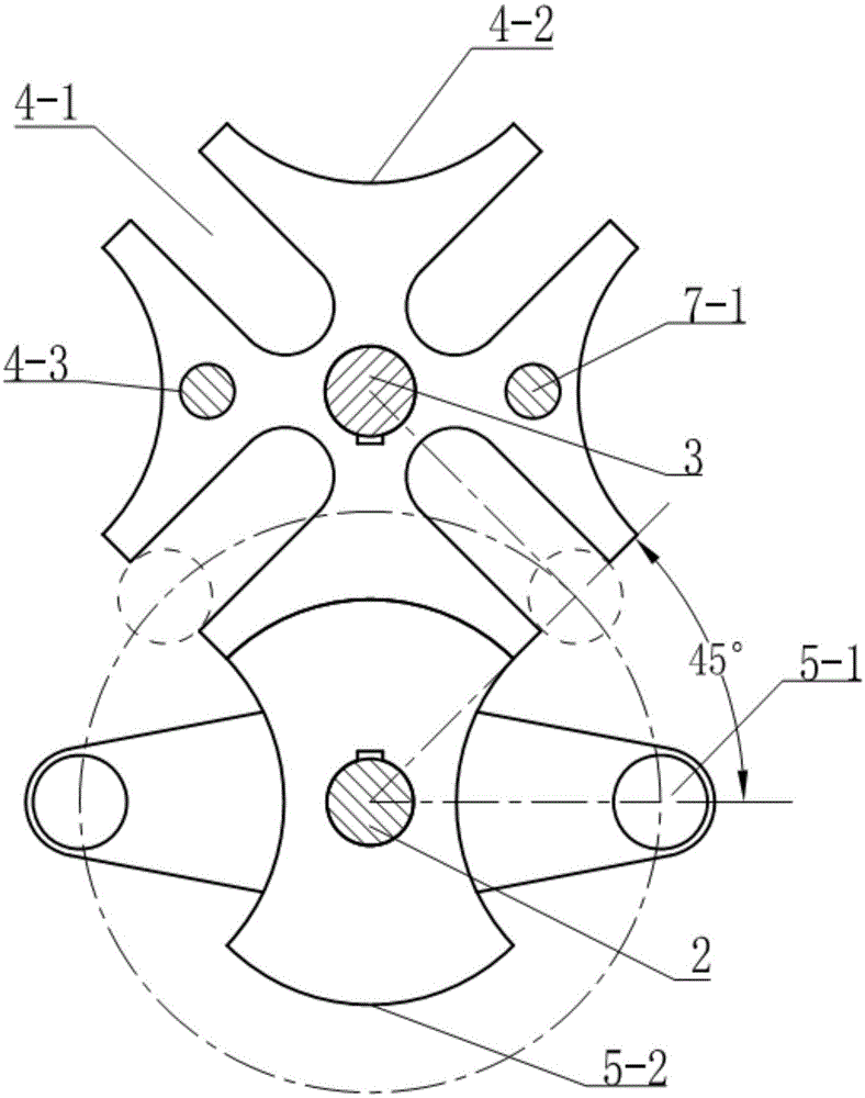
[0028] The transmission mechanism is an externally engaged sheave mechanism (see figure 2 ), the sheave mechanism includes an outer sheave 4 fixed on the second transmission shaft 3 and coaxial with the second transmission shaft 3 and a dial 5 fixed on the first transmission shaft 2 and coaxial with the first transmission shaft 2, The sheave has four dial grooves 4-1 evenly distributed around its axis, a concave locking arc 4-2 is arranged between any two dial grooves 4-1, and the end surface of the outer sheave 4 is provided with Two positioning holes 4-3;...

example 2

[0034] See Figure 9-11 , The dial has a section of convex locking arc 5-2 and two shift pins 5-1, the two shift pins 5-1 are rolling bearings whose inner ring is fixed on the dial 5, and the two shift pins 5 The angle between -1 and the center of rotation of dial 5 is 90 degrees;

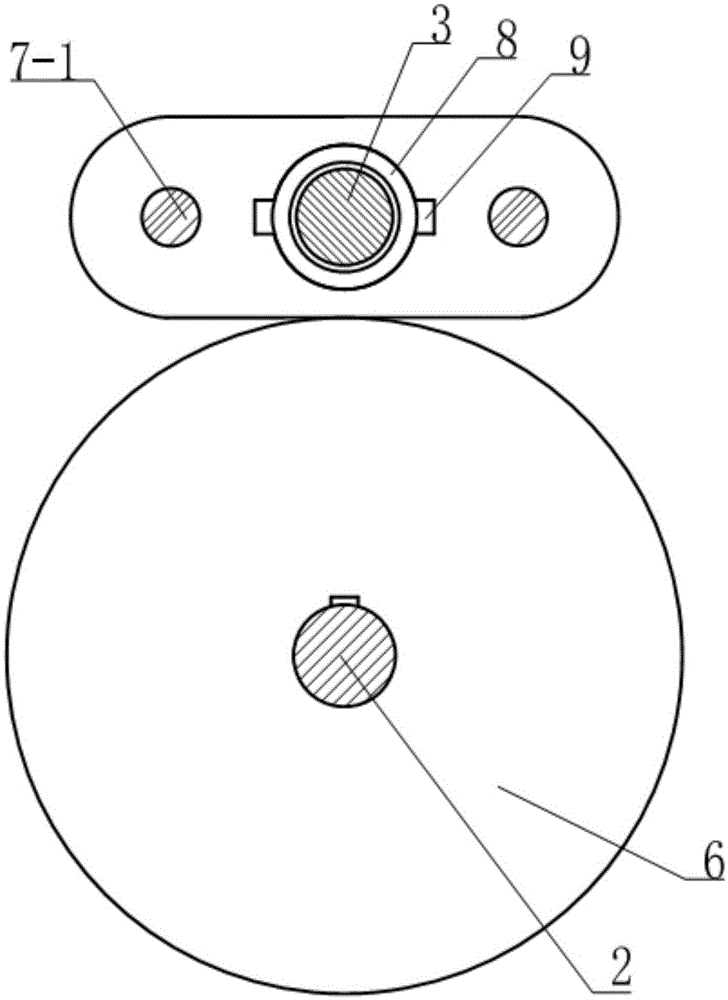
[0035] See Picture 12 , The roller 7-3 moves in the curved groove 6-1, and the trajectory traced by its center is the theoretical profile c of the cylindrical cam 6, which is completely from the positioning pin 7-1. When the positioning hole 4-3 is inserted, the center position of the roller 7-3 is expanded, and the positioning pin 7-1 exits the process transition section of the positioning hole 4-3 (abscissa 0°~90°), and the end surface of the cylindrical cam 6 The parallel working section (abscissa 90°~270°) and the return transition section (abscissa 270°~360°) where the positioning pin 7-1 enters the positioning hole 4-3; the starting point of the process transition section to the The working d...

example 3

[0039] This example is a grinding machine whose worktable can be turned upside down by using the sheave wheel turning device of the present invention.

[0040] See Figure 13 with 14 The grinding machine in this example uses the Venturi jet 10 to suck and spray the grinding liquid mixed with steel balls stored in the mixing tank 12 to the surface of the workpiece, and then grind the surface of the workpiece. In order to prevent the grinding fluid from accumulating in the upward concave surface of the workpiece and hindering further processing, the grinding machine in this example has a turning table which includes a sheave turning device with auxiliary positioning as shown in Example 1. The box body 1 of the sheave turning device is fixed on the side of the frame 14 of the grinder, and one end of the second drive shaft 3 extends directly above the recovery funnel 15 located inside the frame 14, which extends to the inside of the frame 14. A T-slot worktable 11 is provided on the ...


PUM


Abstract

The invention relates to a groove wheel turnover device with an auxiliary positioning function. The groove wheel turnover device comprises a box body, a transmission mechanism driving a workpiece to turn over and an auxiliary positioning mechanism; the transmission mechanism is an external gearing groove wheel mechanism, and the mechanism comprises an outer groove wheel with four pull grooves and a pull disk with two pull pins; and the auxiliary positioning mechanism is a direct driving push rod cylindrical cam mechanism, the cam mechanism comprises a cylindrical cam and a driven body, the cylindrical cam and the pull disk are arranged coaxially, the peripheral face of the cylindrical cam is provided with a curved concave groove, the driven body is driven by the cylindrical cam to conduct reciprocating motion in the axial direction of the cylindrical cam, the driven body can be driven to conduct auxiliary positioning of the groove wheel at a suitable position by the synchronous rotation of the cylindrical cam and the pull disk rotate, and the groove wheel turnover device has the beneficial effects that the positioning precision is high, and the positioning is reliable.

Description

Technical field [0001] The invention relates to a workpiece handling device related to a machine tool, which can turn a workpiece at 180° so as to obtain a required workstation. Background technique [0002] In the industrial production process, it is often necessary to turn the workpiece 180° to obtain a better processing station. Mechanisms that can achieve this flipping action include rack and pinion transmission mechanisms, worm gear transmission mechanisms, and gear transmission mechanisms. Turbine and worm transmission mechanisms and gear transmission mechanisms often need to cooperate with high-precision servo motors to control the flip angle, which is costly; rack and pinion mechanisms often need to cooperate with linear cylinders to control the flip angle, which has a large impact and insufficient positioning accuracy. [0003] The utility model patent application with the authorized announcement number CN201342591Y discloses "a sheave wheel turning mechanism", which uses...

Claims


Application Information

Patent Timeline
Patent Type & Authority Applications(China)
IPC IPC(8): B23Q1/25B23Q5/34B24B37/07B24B47/04
CPCB23Q1/25B23Q5/34B24B37/07B24B47/04
Inventor 陶建华张剑辉关焯辉刘晓初
Owner GUANGZHOU UNIVERSITY
Why Eureka
Try Eureka