A surface strengthening grinding machine with a worktable that can be turned up and down

A surface strengthening and workbench technology, which is applied in the direction of grinding machine tools, grinding devices, manufacturing tools, etc., can solve the problems of affecting the processing accuracy of the grinding machine, affecting the positioning reliability, and insufficient positioning accuracy, so as to achieve the effect of reliable positioning

Active Publication Date: 2017-05-10
GUANGZHOU UNIVERSITY
View PDF6 Cites 0 Cited by
  • Summary
  • Abstract
  • Description
  • Claims
  • Application Information

AI Technical Summary

Problems solved by technology

However, due to the influence of processing and assembly precision, there must be a certain gap between the concave and convex locking arcs of the above-mentioned sheave turning mechanism. The disadvantage of insufficient precision seriously affects the reliability of positioning
And then affect the precision of grinding machine processing

Method used


Image

  • A surface strengthening grinding machine with a worktable that can be turned up and down
  • A surface strengthening grinding machine with a worktable that can be turned up and down
  • A surface strengthening grinding machine with a worktable that can be turned up and down

Examples


example 1

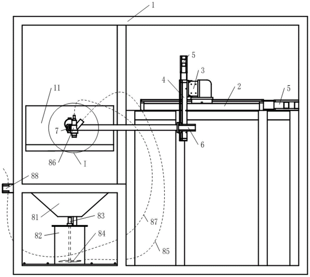
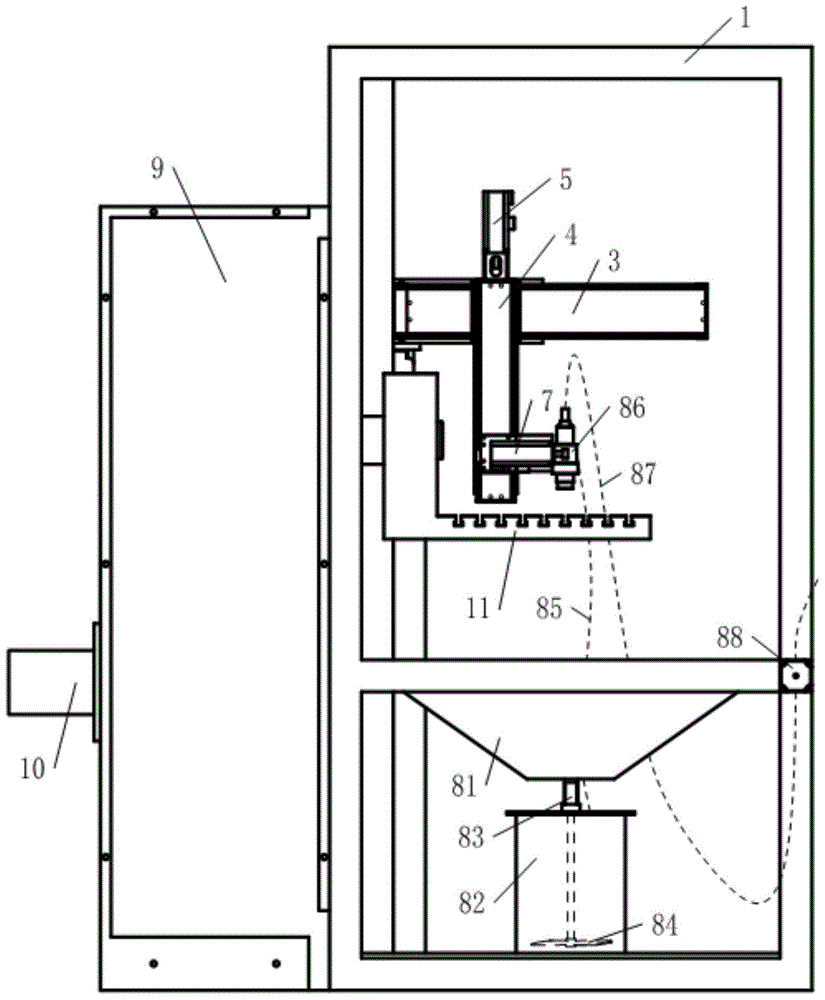
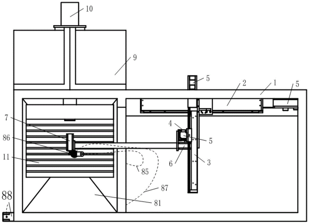
[0033] see Figure 1~3 and 5, the rear side of the frame 1 in this example is provided with a fixed frame for fixing the screw drive system, and the left part is provided with a funnel platform for fixing the grinding liquid recovery funnel 81, and the screw drive system is fixed on the X-axis ball screw pair 2 on the fixed frame, Y-axis ball screw pair 3 fixed on the slider of X-axis ball screw pair 2, and Z-axis fixed on the slider of Y-axis ball screw pair 3 Ball screw pairs 4 are formed; the moving directions of the three groups of ball screw pairs are perpendicular to each other, and a servo motor 5 is connected to the lead screw of each group of screw pairs. The slider of the Z-axis ball screw pair 4 is provided with a first corner motor 6 whose rotating shaft is parallel to the moving direction of the X-axis ball screw pair 2, and the rotating shaft of the first corner motor 6 passes through a The long rod is suspended with a second angle motor 7 whose rotating shaft i...

example 2

[0045] The difference between this example and Example 1 is that the structures of the mechanisms inside the drive box are different.

[0046] see Figure 16 and 17 , the dial has a convex locking arc 952 and two dial pins 951, the two dial pins 951 are rolling bearings whose inner rings are fixed on the dial 95, and the two dial pins 951 and the rotation center of the dial 95 The angle between the connecting lines is 90 degrees;

[0047] see Figure 18 , the roller 973 moves in the curved groove 961, and the track traced by its center is the theoretical profile c of the cylindrical cam 96, when the theoretical profile c is completely inserted into the positioning hole 943 from the positioning pin 971 The center position of the roller 973 is unfolded, the process transition section (abscissa 0°-90°) exiting the locating hole 943 from the locating pin 971, and the working section parallel to the end face of the cylindrical cam 96 (abscissa 90°-270°) It is composed of the re...


PUM


Abstract

The invention discloses a surface strengthening grinding machine whose workbench can be turned up and down. The grinder includes a frame, a workbench, an XYZ three-axis motion system and a rotation system for controlling a Venturi injector; Positioned sheave turning device and slurry circulation system; wherein, said sheave turning device with auxiliary positioning includes a box body, an external meshing sheave mechanism with two pins and four grooves inside the box body, and a straight-moving push rod type cylinder cam mechanism. The grinding liquid circulation system includes a grinding liquid recovery funnel, a stirring device and a Venturi injector located directly under the workbench. The mixing tank is connected. The grinding machine of the invention can not only turn the workpiece 180°, but also has the advantages of high positioning accuracy and reliable operation.

Description

technical field [0001] The invention relates to an abrasive jetting machine tool, in particular to a grinding fluid jetting machine tool, which can perform intensive grinding on the surface of a workpiece. Background technique [0002] The surface quality of mechanical parts directly affects the performance, life and reliability of mechanical equipment; however, mechanical parts are affected by cutting heat during the cutting process, and inevitably form a tensile stress metamorphic layer on the surface of the workpiece, which makes the workpiece The surface is prone to fatigue cracks, which reduces the fatigue life and reliability of components. [0003] Many mechanical parts often require relatively comprehensive surface quality, that is, the surface of the workpiece has high hardness and low surface roughness at the same time. In order to obtain such surface quality, higher hardness is often obtained through surface coating, surface modification or surface mechanical str...

Claims


Application Information

Patent Timeline
Patent Type & Authority Patents(China)
IPC IPC(8): B24B37/00B24B37/34B24B57/02B24B57/00
CPCB24B37/00B24B37/34B24B57/00B24B57/02
Inventor 陶建华张剑辉关焯辉刘晓初
Owner GUANGZHOU UNIVERSITY
Why Eureka
Try Eureka