Position sensing mechanism

A coding element and magnetoresistive technology, applied in the field of position sensing mechanism, can solve problems such as low sensitivity, Hall sensing elements are difficult to meet the needs of the industry, and the degree of accuracy affects the accuracy of position discrimination.

Pending Publication Date: 2022-07-19
HIWIN MIKROSYST
View PDF3 Cites 0 Cited by
  • Summary
  • Abstract
  • Description
  • Claims
  • Application Information

AI Technical Summary

Problems solved by technology

The above-mentioned technical means of using the Hall element as the magnetic sensing element is certainly a common technology in the position sensing technology, but because the Hall element itself has high power consumption and low sensitivity, it is difficult to use the Hall element as a position sensing device. There are still limitations on components, especially in applications that require low power consumption and high sensing sensitivity, Hall sensing components have been difficult to meet the needs of the industry
[0003] Further in the prior art, it is as figure 1 As disclosed in the US10480963 patent, although it also utilizes the Hall sensor 1 as the sensing element of the absolute column magnetic track 2, but in the sensing of the incremental column magnetic track 3, an automatic sensor is used. Relatively low power consumption and high sensitivity magnetoresistive elements such as spin-valve tunneling magneto-resistance (SV TMR) or anisotropic magneto-resistance (AMR) are used as sensing elements. In order to obtain better sensing sensitivity, the spin-valve tunneling magnetoresistive element 4 or anisotropic magnetoresistive element obtains the position by sensing the change of the magnetic field angle caused by the movement of the magnetic track. In order to accurately sense the change of the magnetic field angle in the incremental column magnetic track, it is necessary to make the film surface of the spin-valve tunneling magnetoresistive element or anisotropic magnetoresistive element be located on the x-z plane, so that As a result, the sensor element of the absolute row on the x-y plane, that is, the Hall sensor 1, is in a spatial state on a different plane, and then it is necessary to assemble each of the absolute row and the incremental row. After the sensing element is manufactured independently as a part, it is individually aligned and then assembled to the substrate (not shown in the figure). In this way, not only the assembly process and cost are increased, but the alignment The degree of accuracy affects the accuracy of position discrimination, making it difficult to effectively improve the yield of products

Method used


Image

  • Position sensing mechanism
  • Position sensing mechanism
  • Position sensing mechanism

Examples


Embodiment Construction

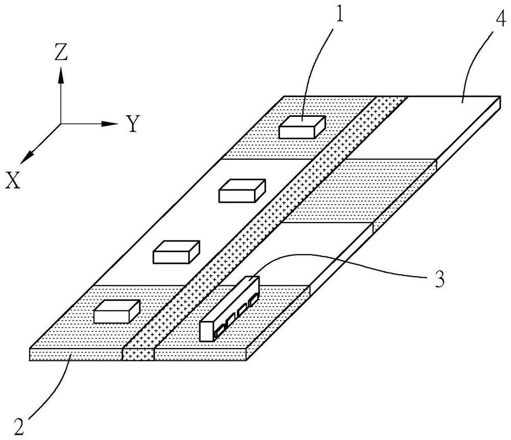
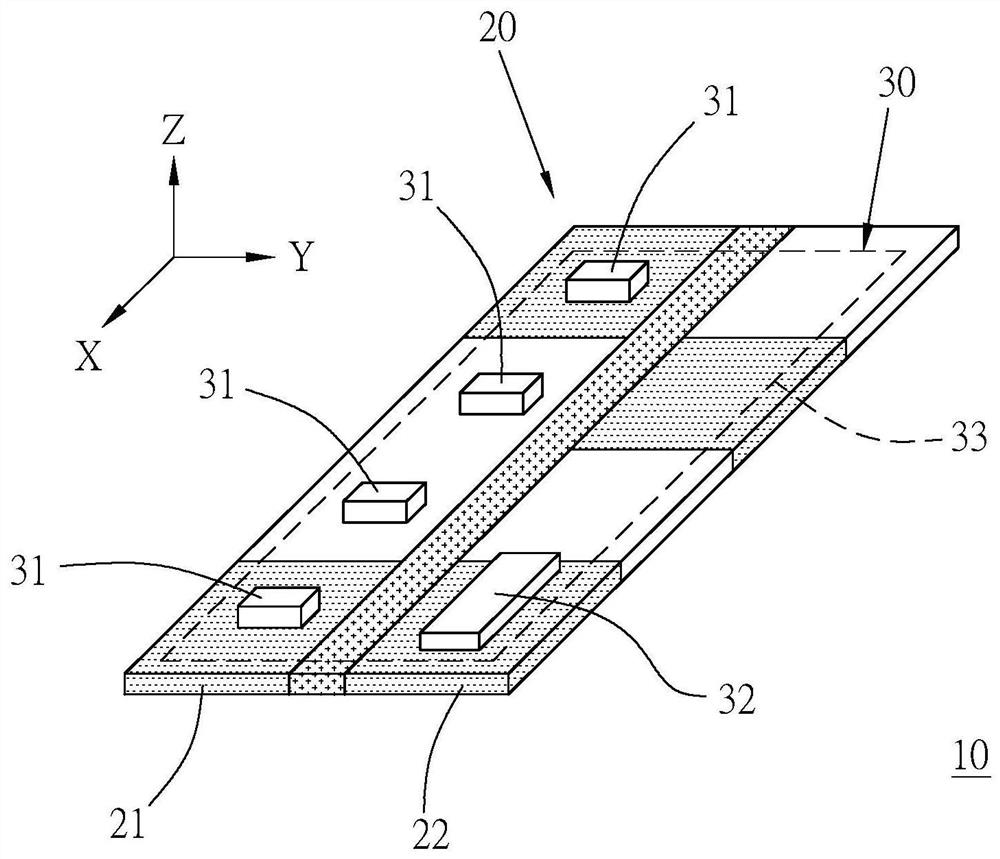
[0028] First, see figure 2 As shown, the position sensing mechanism 10 provided in a preferred embodiment of the present invention mainly includes an encoding element 20, a reading element 30 and a processing unit (not shown in the figure).

[0029] The encoding element 20 is based on the existing magnetic scale technology with a magnetic field as a signal source. The column tracks 22 extend parallel to each other along a virtual axis of movement, and as figure 2 The shown x-y plane changes the magnetic poles according to the preset coding method. Generally speaking, the moving axis is usually linear and is consistent with the length direction of the magnetic ruler. Since the magnetic scale technology related to the incremental row magnetic track 22 belongs to the prior art content known to those skilled in the art to which the present invention pertains before the application of the present invention, its specific magnetic pole arrangement, manufacturing process or related...


PUM


Abstract

The invention provides a position sensing mechanism, which comprises a coding element used as a sensing signal source, a reading element used for sensing a signal of the signal source, and a processing unit used for receiving and analyzing a sensing signal output by the reading element, the reading element is technically characterized in that a magnetoresistance unit used for sensing a signal source signal in the reading element is a tunneling magnetoresistance (TMR), the magnetic moments of a reference layer and a free layer of the tunneling magnetoresistance are perpendicular to each other, the magnetic moment of one of the reference layer and the free layer which are perpendicular to each other is parallel to a film surface, and the magnetic moment of the other layer is parallel to a film surface, and the magnetic moment of the other layer is parallel to the film surface. And the magnetic moment of the other layer is vertical to the film surface.

Description

technical field [0001] The present invention is related to sensing technology, and more particularly, to a position sensing mechanism which utilizes tunneling magnetoresistance for position sensing. Background technique [0002] The sensing technology for performing position analysis by sensing the changes of specific signals such as magnetism or light in the coding element under the position change is a widely used technical means in the prior art. Specifically, for example, in the previous case of US6100681A, two sets of Hall sensing chips with a relative position difference of 90 degrees are used to sense position changes along a moving direction. Or as disclosed in the US20090102461A patent publication, in the technology provided by the coding element, which uses the magnetism as the signal source, the two magnetic tracks it has are set to the binary system and the decimal system respectively, and then use the majority The discrete Hall sensing elements of the device se...

Claims


Application Information

Patent Timeline
IPC IPC(8): G01D5/245
CPCG01D5/2455
Inventor 赖志煌李佳璋徐志豪萧恆昇
Owner HIWIN MIKROSYST
Why Eureka
Try Eureka