Body in white bend resistance structure and arrangement mode thereof

A body-in-white, anti-bending technology, applied in the direction of load-bearing body structure, superstructure, superstructure sub-assembly, etc., can solve the problem of poor bearing capacity and bending resistance, no good bending resistance, water tank bracket assembly Self-weight and other problems, to achieve high bending resistance, good bending effect, and increase the effect of bending resistance

Active Publication Date: 2015-11-04
CHINA AUTOMOTIVE ENG RES INST
View PDF10 Cites 25 Cited by
  • Summary
  • Abstract
  • Description
  • Claims
  • Application Information

AI Technical Summary

Problems solved by technology

The angle of the outer panel of the B-pillar of the original structure and the overlapping effect of the outer panel and the connecting parts did not form a good bending performance
At the same time, the layout of the transverse and longitudinal beams of the body-in-white does not form a closed structure, and the bending resistance is poor
The traditional body-in-white water tank bracket assembly is heavy in weight, and the upper and lower beams are thicker. Although it has good load-bearing performance, the mass of the excitation end of the body-in-white is heavy, which will arouse the overall bending mode, and the bending resistance is also weak.
The connection structure between the longitudinal beam of the water tank and the front bumper and the front longitudinal beam is weak, and its installation structure is simple, and its bearing capacity and bending resistance are poor

Method used


Image

  • Body in white bend resistance structure and arrangement mode thereof
  • Body in white bend resistance structure and arrangement mode thereof
  • Body in white bend resistance structure and arrangement mode thereof

Examples


Embodiment Construction

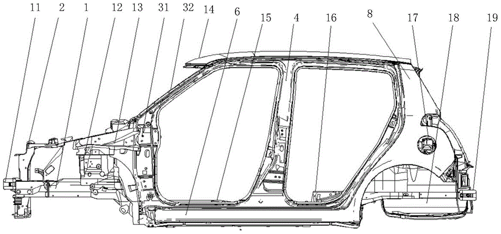
[0064] The implementation of the present invention will be illustrated by specific specific examples below, and those skilled in the art can easily understand other advantages and effects of the present invention from the contents disclosed in this specification. The front, rear, left, and right orientations involved in the present invention all take the body in white as a reference, and the normal driving direction is the front.

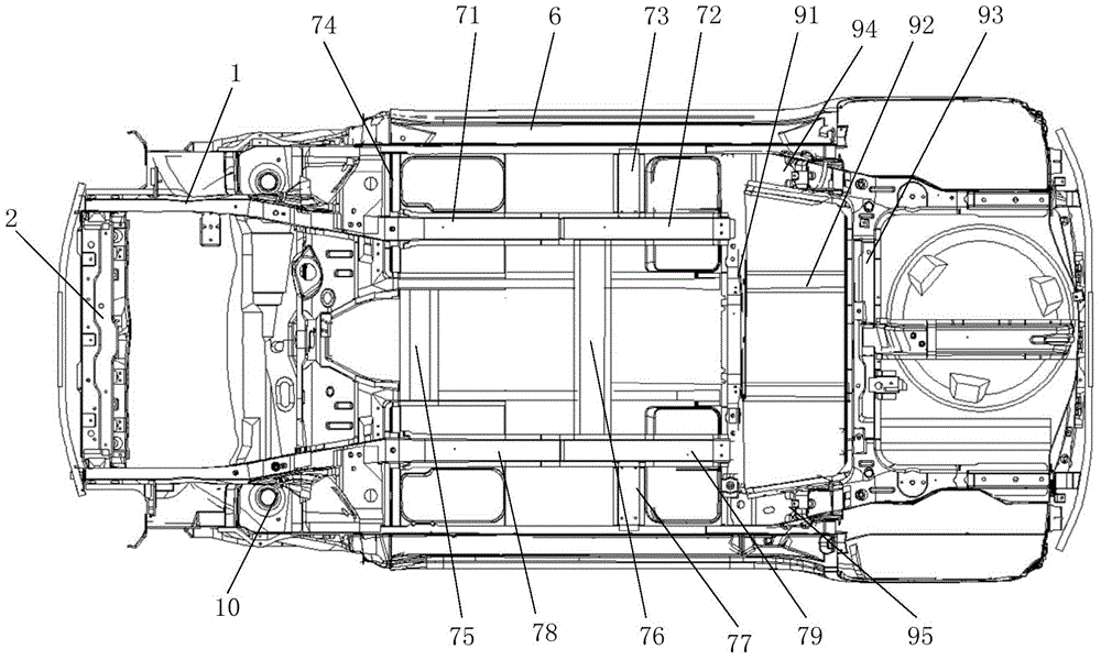
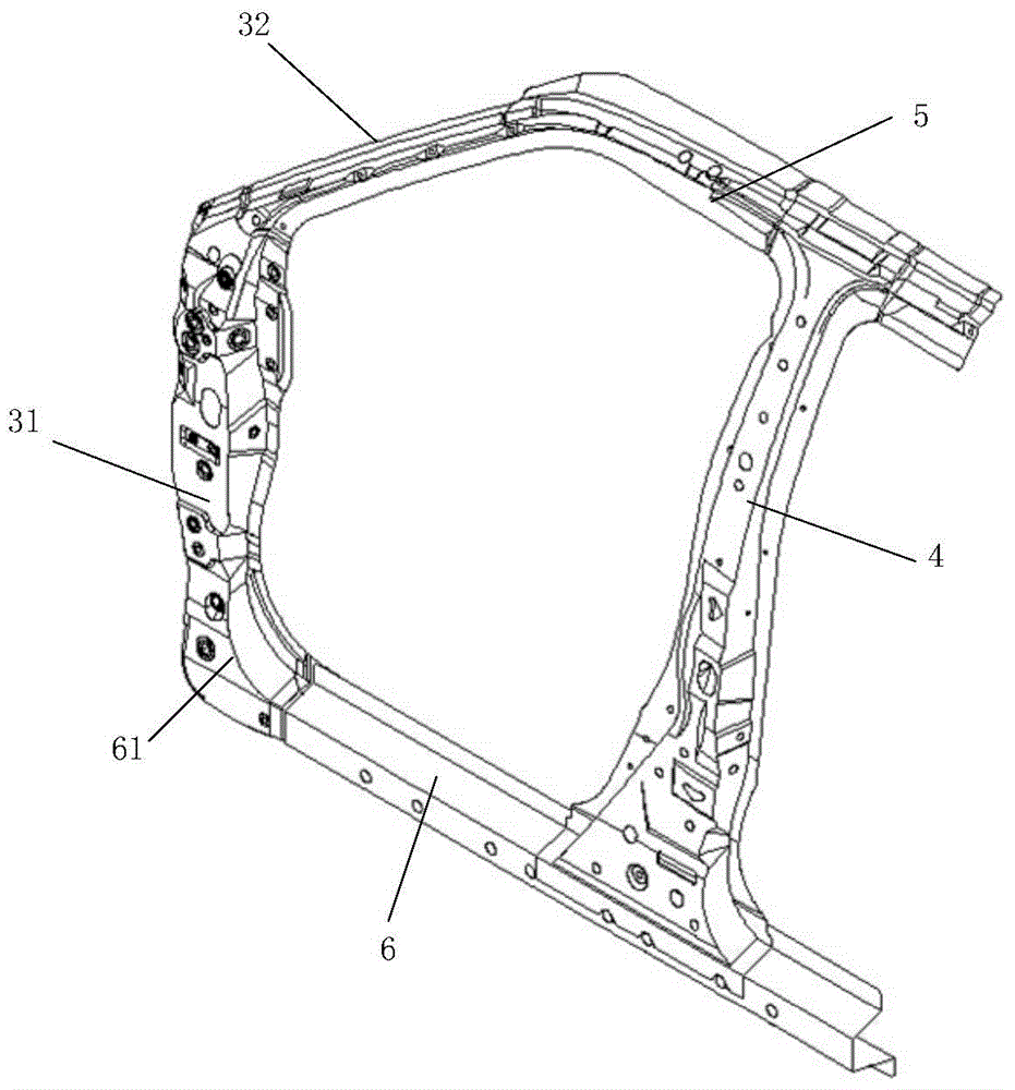
[0065] The present invention provides a body-in-white anti-bending structure. In the embodiment of the present invention, the following body-in-white is taken as an example for structural description. The structure of the body-in-white is as follows: figure 1 and figure 2 As shown, its main structure and its assembly are composed of the following parts: front bumper 11, water tank bracket assembly 1, front longitudinal beam 2, engine suspension mounting bracket assembly 12, dash panel 13, A-pillar assembly Cheng 3, B-pillar assembly 4, B-pillar up...


PUM


Abstract

The invention provides a body in white bend resistance structure and an arrangement mode thereof. The lower end of a lower vertical plate of a column A is in overlap connection with a sill strip. The upper end of the lower vertical plate of the column A is in overlap connection with an outer plate of the column A. The outer plate of the column A is in overlap connection with an upper beam of a column B. The upper end of an outer plate of the column B is in overlap connection with the upper beam of the column B. The lower end of the outer plate of the column B is in overlap connection with the sill strip. Two to three layers of spot welding connection is formed at each overlap joint to form a closed structure. The bend resistance section of the sill strip, the bend resistance section of the vertical plate of the column A, the bend resistance section of the outer plate of the column A and the bend resistance section of the upper beam of the column B are each in a closed annular shape. Due to the fact that the bend resistance sections form the closed annular shapes and are composed of three or four sheet metal parts, the bend resistance is improved; due to extending sections at the upper and lower ends of the outer plate of the column B, the overlap connection efficiency of the upper beam and the sill strip of the column B and the outer plate of the column B is enhanced, and the bend resistance performance is improved; the transverse and longitudinal staggered closed structure has the effect of enhancing inertia torque, and the bend resistance performance is improved.

Description

technical field [0001] The invention relates to the technical field of automobile body structures, in particular to a body-in-white anti-bending structure and its arrangement. Background technique [0002] The key component on the force transmission path of the automobile body is the main structure of the vehicle body, which is responsible for the force bearing and energy absorption during the vehicle collision process, and is the main determinant of whether the collision vehicle can obtain a high-star safety evaluation. The rationality, utility, and process realization of the design are the main factors affecting the collision result. The structural design on the force transmission path is not accomplished overnight, and requires repeated attempts, improvements, optimizations, and verifications to achieve the best design effect. [0003] In the traditional car body-in-white structure, the angle between the outer panel of the B-pillar and the height direction of the vehicle...

Claims


Application Information

Patent Timeline
Patent Type & Authority Applications(China)
IPC IPC(8): B62D23/00B62D25/02B62D25/04B62D25/08B62D25/20
Inventor 苏锦涛邓兆祥赵芸骁张秋颖
Owner CHINA AUTOMOTIVE ENG RES INST
Why Eureka
Try Eureka