

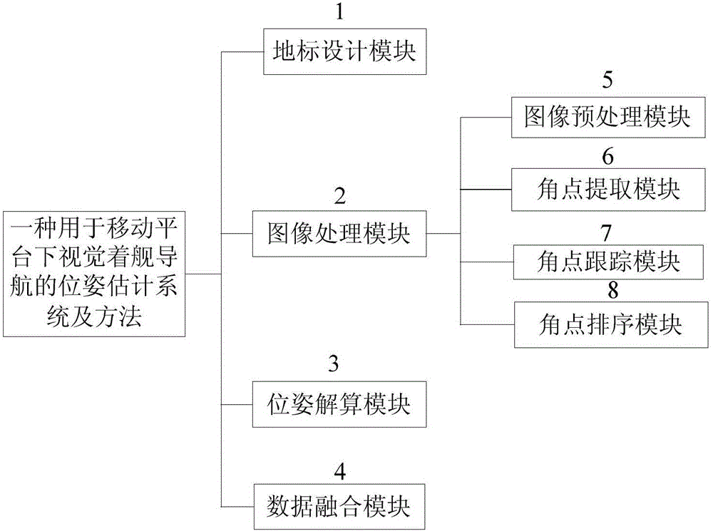
Pose estimation system and method for visual carrier landing navigation on mobile platform
A pose estimation algorithm and pose estimation technology, applied in the field of pose estimation systems, can solve problems such as inability to complete landing tasks, inability to provide UAV navigation information, and large amount of 3D reconstruction calculations
- Summary
- Abstract
- Description
- Claims
- Application Information
AI Technical Summary
Problems solved by technology
Method used
Image

Examples
Embodiment Construction
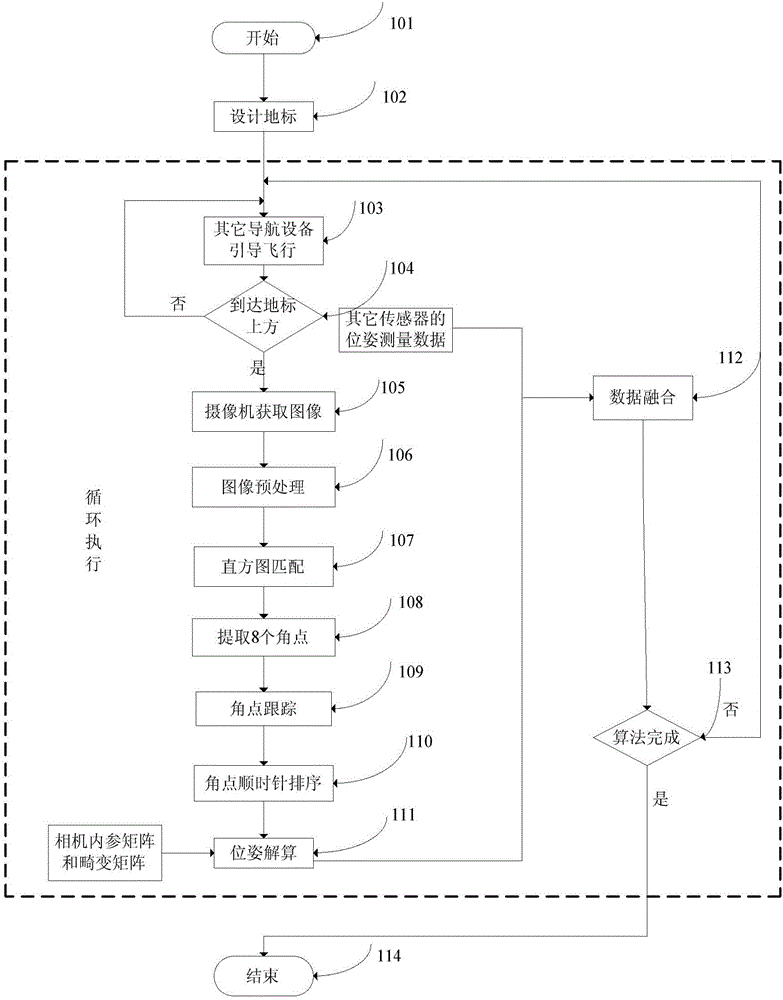
[0046] Such as figure 1 As shown, a pose estimation method for visual landing navigation, the specific steps are:
[0047] Step 101: Start to estimate the pose of the UAV visual landing navigation;
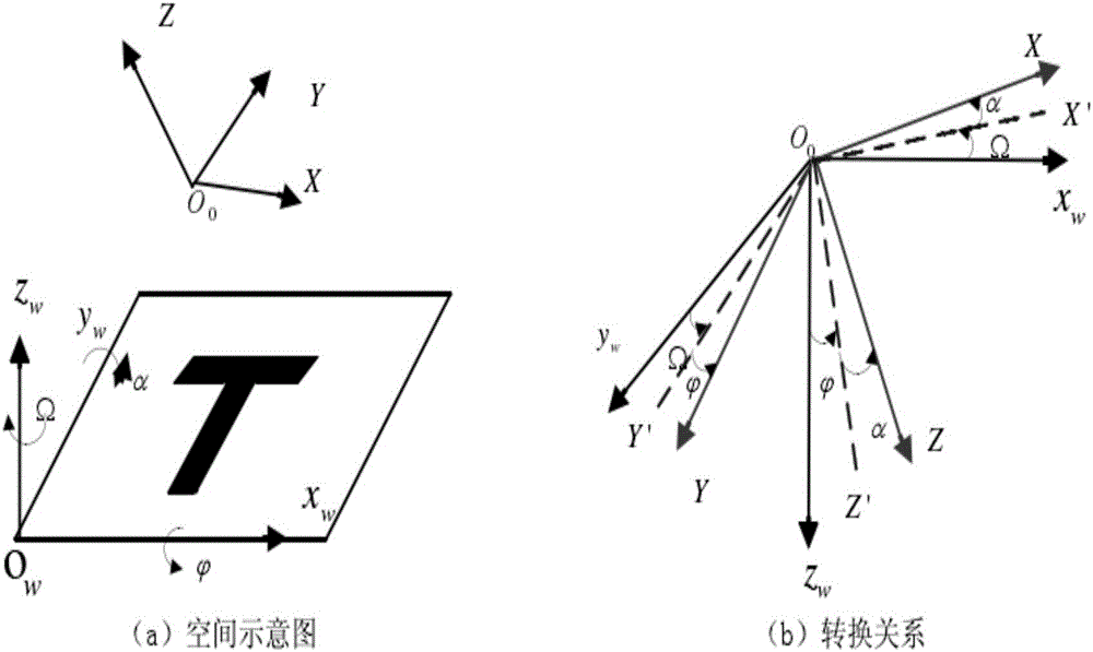
[0048] Step 102: Design a black "T"-shaped landmark consisting of two rectangles with a length of 3 meters and a width of 1 meter; when facing the landmark, the upper left corner is set as the origin of the landmark coordinate system, and the coordinates are (0,0);
[0049] Step 103: the integrated navigation mode composed of global positioning system navigation and inertial navigation guides the unmanned aerial vehicle to fly;
[0050] Step 104: Determine whether the UAV has reached the sky above the landing landmark through target matching, if so, perform step 105, otherwise perform step 103, and continue to guide the flight;
[0051] Step 105: the camera acquires images;
[0052] Step 106: Perform binarization, morphological operations, and contour extraction processing on t...
PUM
 Abstract
Description
Claims
Application Information