Novel cylindrical battery stacking packing structure

A group structure, cylindrical technology, applied in the direction of battery pack components, secondary batteries, structural parts, etc., can solve the problems of large volume occupied by batteries, low energy density of batteries, and many hours of execution, so as to achieve easy installation, The effect of compact structure and high energy density

Inactive Publication Date: 2015-11-04
何健舟
View PDF6 Cites 3 Cited by
  • Summary
  • Abstract
  • Description
  • Claims
  • Application Information

AI Technical Summary

Problems solved by technology

During the grouping process, the axial direction of the battery is installed in the circular fixing holes of the upper and lower cover plates. When the number of batteries connected in parallel is large, it depends on the machining accuracy to ensure the precise cooperation between the battery and the upper and lower cover plates. Machining errors lead to this There are many man-hours for process execution and low installation efficiency; each small battery module requires a clamping design of the upper and lower cover plates, the unit battery occupies a large volume, and the energy density of the battery is low

Method used


Image

  • Novel cylindrical battery stacking packing structure
  • Novel cylindrical battery stacking packing structure
  • Novel cylindrical battery stacking packing structure

Examples


Embodiment Construction

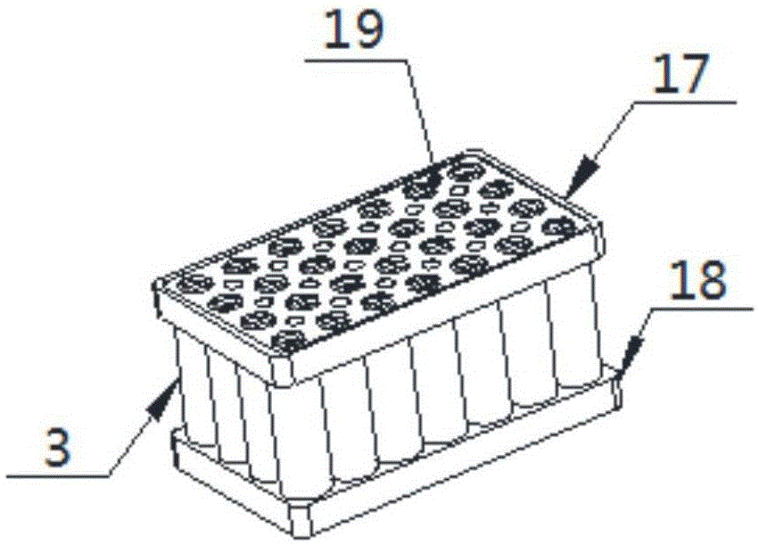
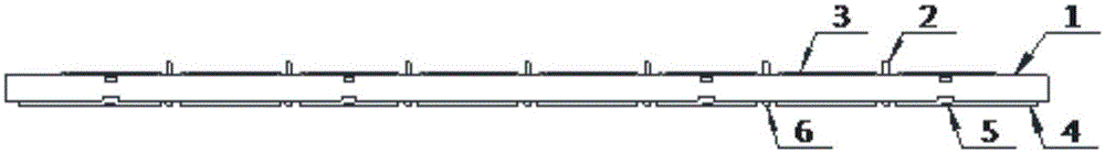
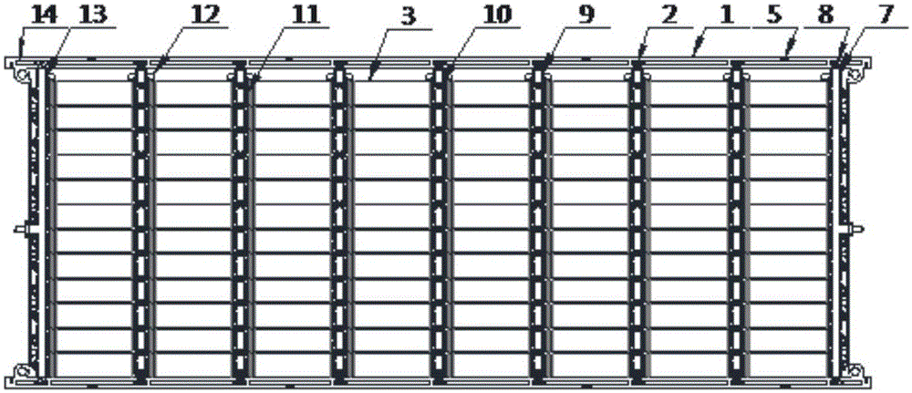
[0020] Such as figure 1 As shown, the new cylindrical battery stacking group structure includes a grouped single frame, and several battery support structures are neatly arranged on the grouped single frame, and the upper end surface of the grouped single frame is provided with upper and lower layers Parallel columns, the lower end surfaces of the frame of the grouped single frame are provided with upper and lower layer locking structures and accumulating strips, and the upper and lower end faces of the outermost frame of the grouped single frame are respectively provided with upper and lower alignment structures 1 and 2; The left and right sides of the grouped monomer frame are respectively equipped with positive and negative electrode series copper bars, and the positive and negative electrode series copper bars are respectively fixed on the grouped monomer frame by compression screws; the two ends of each battery support structure are respectively installed with conductive ...


PUM


Abstract

The invention discloses a novel cylindrical battery stacking packing structure. The novel cylindrical battery stacking packing structure comprises a monomer packing framework and battery support structures, wherein upper-lower layer parallel posts are arranged on the upper end face of the border of the monomer packing framework; upper-lower layer locking structures and current accumulation bar press bars are arranged on the lower end face of the border of the monomer packing framework; a positive electrode serial-connection copper bar and a negative electrode serial connection copper bar are arranged on the left and right sides of the monomer packing framework respectively; the positive electrode serial-connection copper bar and the negative electrode serial-connection copper bar are fixed to the monomer packing framework through compression screws; conductive domes are arranged at the two ends of each battery support structure respectively; current accumulation PCB (Printed Circuit Board) bars are arranged between columns of the battery support structures; each current accumulation PCB bar is in compression joint with the current-conducting elastic sheet in the same column; and the upper-lower layer parallel posts of the upper layer monomer packing framework are pressed against the current accumulation PCB bars of the lower layer monomer packing framework. Batteries are directly snapped into on the monomer packing framework and connected in series and in parallel without welding, so that the novel cylindrical battery stacking packing structure has the advantages of convenience in installation, high assembly efficiency, small unit battery duty ratio and high energy density.

Description

technical field [0001] The invention mainly relates to the field of batteries, in particular to a novel stacked structure of cylindrical batteries. Background technique [0002] Existing cylindrical battery group structure see figure 1 As shown, the upper cover plate 17 and the lower cover plate 18 clamp and assemble the cylindrical battery 3 , and connect the circuit in series and parallel by welding the accumulator plate 19 . The placement position of the battery is arranged along the normal direction of the upper and lower cover plates. During the grouping process, the axial direction of the battery is installed in the circular fixing holes of the upper and lower cover plates. When the number of batteries connected in parallel is large, it depends on the machining accuracy to ensure the precise cooperation between the battery and the upper and lower cover plates. Machining errors lead to this The process requires more man-hours and lower installation efficiency;...

Claims


Application Information

Patent Timeline
Patent Type & Authority Applications(China)
IPC IPC(8): H01M2/10H01M2/20H01M10/44H01M10/613H01M10/617H01M10/643H01M50/213H01M50/244H01M50/509H01M50/519
CPCH01M10/44H01M50/20H01M50/502Y02E60/10
Inventor 何健舟
Owner 何健舟
Why Eureka
Try Eureka