Constant voltage output pulsed power supply with duty ratio adjustable range being 20%-80%

A technology of constant voltage output and pulse power supply, which is applied in the field of switching power supply, can solve problems affecting production efficiency and achieve the effect of improving production efficiency and reducing labor costs

Inactive Publication Date: 2015-11-04
常州大控电子科技有限公司
View PDF12 Cites 2 Cited by
  • Summary
  • Abstract
  • Description
  • Claims
  • Application Information

AI Technical Summary

Problems solved by technology

[0003] The unipolar pulse bias power supply for plasma coating equipment requires constant output pulse voltage, adjustable pulse width of 20%-80%, and power of 30KW. According to different workpieces and different coating materials, the pulse duty cycle needs to be 20%. Set within the range of -80%, the model of

Method used


Image

  • Constant voltage output pulsed power supply with duty ratio adjustable range being 20%-80%
  • Constant voltage output pulsed power supply with duty ratio adjustable range being 20%-80%

Examples


Embodiment 1

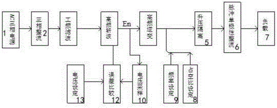
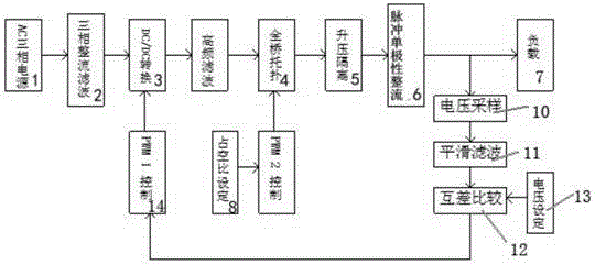
[0015] See figure 1 and figure 2 As shown, a constant voltage output pulse power supply with an adjustable duty ratio ranging from 20% to 80%, including an AC three-phase power supply 1, a three-phase rectification filter circuit 2, a DC / DC conversion circuit 3, a full bridge topology circuit 4, Boost isolation circuit 5, pulse unipolar rectification 6, the control signal output end of the AC three-phase power supply 1 is connected to the control signal input end of the three-phase rectification filter circuit 2, the control signal of the three-phase rectification filter circuit 2 The output terminal is connected to the input terminal of the DC / DC conversion circuit 3, and a full-bridge topology circuit 4 is connected between the DC / DC conversion circuit 3 and the boost isolation circuit 5, and the control signal output terminal of the boost isolation circuit 5 It is connected to the control signal input end of the pulse unipolar rectification 6 , and the control signal outp...

Embodiment 2

[0017] See figure 1 Shown is the unipolar pulse bias power supply of USER model BR-30A, which samples the DC voltage En after the DC / DC conversion circuit 3 and feeds it back to the mutual difference comparator 12 to compare and convert with the external set voltage. Form a series of unequal width pulse signals to control the opening and closing of the full-bridge switch tube to achieve the purpose of constant voltage. Its constant voltage is the DC voltage En after the constant DC / DC conversion circuit 3, not the voltage at the output terminal, because In this way, when the duty cycle of the output pulse is adjusted, the output power will change accordingly, and the smaller the duty cycle, the smaller the output power.


PUM


Abstract

The present invention discloses a constant voltage output pulsed power supply with a duty ratio adjustable range being 20%-80%. The constant voltage output pulsed power supply comprises an AC three-phase power supply, a three-phase rectifier and filter circuit, a DC/DC conversion circuit, a full bridge topology circuit, a boost isolation circuit and a pulse unipolarity rectifier, wherein a control signal output end of the AC three-phase power supply is connected with a control signal input end of the three-phase rectifier and filter circuit, a control signal output end of the three-phase rectifier and filter circuit is connected with an input end of the DC/DC conversion circuit, the full bridge topology circuit is connected between the DC/DC conversion circuit and the boost isolation circuit, a control signal output end of the boost isolation circuit is connected with a control signal input end of the pulse unipolarity rectifier, and a control signal output end of the pulse unipolarity rectifier is connected with a load. With adoption of the constant voltage output pulsed power supply, the problem of output voltage reduction when a small duty ratio of a conventional unipolar pulse bias power supply is set is solved, the production efficiency is raised and the labor cost is reduced.

Description

technical field [0001] The invention relates to the field of switching power supplies, in particular to a constant-voltage output pulse power supply with an adjustable duty ratio ranging from 20% to 80%. Background technique [0002] During the pulse electroplating process of the pulse power supply, when the current is turned on, the pulse (peak) current is equivalent to several times or even dozens of times of the ordinary DC current. It is this instantaneous high current density that makes the metal ions reduce under extremely high overpotential , so that the grains of the deposited layer become thinner; when the current is turned off, the discharge ions near the cathode area return to the initial concentration, and the concentration polarization is eliminated, which is beneficial to continue to use high pulse (peak) current density in the same period of the next pulse, At the same time, during the shutdown period, there are also phenomena such as recrystallization and ads...

Claims


Application Information

Patent Timeline
IPC IPC(8): H02M9/02
Inventor 刘勤华
Owner 常州大控电子科技有限公司
Why Eureka
Try Eureka